Le Peak Atlas ESR70 gold est une version améliorée du précédent Peak Atlas ESR70 Plus. Il fait tout ce que l’ESR70 Plus a fait mais en mieux.
Il mesure désormais la capacité jusqu'à 10 fois plus rapidement et sur une plage plus large, grâce à de nouveaux algorithmes de test. La mesure de capacité est également beaucoup moins influencée par les résistances parallèles ou les courants de fuite grâce à notre nouveau système de mesure Triple-Slope.
À l'aide des sondes plaquées or fournies (amovibles), l'Atlas ESR70 gold peut mesurer l'ESR jusqu'à une résolution de 0,01 ohms, jusqu'à 40 ohms. Il peut même mesurer l'ESR pour les condensateurs en circuit. Les sondes sont amovibles, permettant d'installer des sondes compatibles de 2 mm. Des alertes sonores sont produites pour différents niveaux ESR, vous permettant d'effectuer de nombreux tests successivement sans avoir à regarder l'écran. L'ESR70 prend automatiquement en compte la réactance capacitive, de sorte que même les condensateurs de faible valeur (jusqu'à 0,3 uF) peuvent mesurer l'ESR avec précision.
Caractéristiques
Utilise une seule pile alcaline AAA (incluse).
LCD alphanumérique avec rétroéclairage.
Analyse automatique - démarrez lorsque vous appliquez les sondes.
Décharge automatique du condensateur grâce à la fonction de décharge contrôlée.
Mesure ESR (et faible résistance CC) (même en circuit).
Réactance capacitive automatiquement prise en compte pour garantir une ESR précise.
Mesure de capacité (si test hors circuit).
Alertes sonores pour différents niveaux ESR.
Plage de mesure ESR étendue jusqu'à 40 Ohms.
Alternatives de sonde en option faciles à installer.
Nouvelles fonctionnalités gold
Écran LCD amélioré avec un meilleur rétroéclairage.
Mesure de capacité 10 fois plus rapide pour les gros condensateurs.
Système d'options utilisateur amélioré.
Nouveau système de mesure à triple pente pour réduire considérablement l'influence de la résistance parallèle et/ou du courant de fuite sur les mesures de capacité.
Plage de mesure de capacité beaucoup plus large, désormais de 0,3 uF à 90 000 uF (au lieu de 1 uF à 22 000 uF).
Caractéristiques
Type d'analyseur
ESR et capacité
Types de composants
Condensateurs (>0,3 uF)
Gamme ESR
0,00 Ohm à 40,0 Ohm
Résolution ESR
À partir de 0,01 Ohm
Utilisation en circuit
ESR uniquement
Plage de capacité
0,3 uF à 90 000 uF
Type de batterie
Pile alcaline AAA 1,5 V (fournie). Durée de vie typique de 1 500 opérations
Type d'affichage
LCD alphanumérique (avec rétroéclairage)
Inclus
Peak Atlas ESR70 gold
Câbles de test extra longs et extra flexibles (450 mm ou câble recouvert de silicone)
Fiches et prises plaquées or 2 mm avec pinces crocodiles plaquées or amovibles
Guide d'utilisation illustré et complet
Pile alcaline AAA
Téléchargements
Fiche technique (EN)
Guide de l'utilisateur (FR)
Guide de l'utilisateur (FR)
Guide de l'utilisateur (informatique)
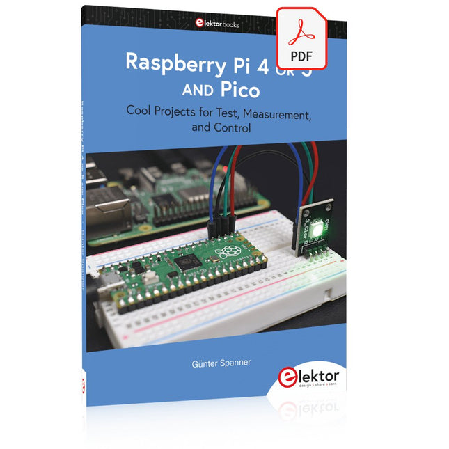
Cool Projects for Test, Measurement, and Control
The Raspberry Pi has dominated the maker scene for many years. Freely accessible I/O pins have made it one of the most popular processor boards of all time. However, the classic Raspberry Pi has no analog inputs. Direct measurement of analog values is therefore not possible. Consequently, photodiodes, NTCs, Hall sensors, etc. cannot be read directly. In addition, the pins are connected directly to the exposed contacts, i.e. without a driver or protection circuit. This can quickly destroy the central controller and thus the entire Raspberry Pi.
These problems can be elegantly solved with the Pico. As a front-end, it can easily handle a wide range of measurement tasks. In addition, the Pico is much cheaper than a classic Raspberry Pi 4 or 5. If a faulty circuit leads to the destruction of the Pico, this is relatively easy to handle. This makes the combination of a classic Raspberry Pi 4 or 5 and the Pico an ideal pair.
The book introduces the broad and highly topical field of modern controller technology using the combined force of a Raspberry Pi 4 or 5 and a Raspberry Pi Pico. In addition to a detailed introduction to the operation and functionality of the controller boards themselves, the book also focuses on data acquisition and processing with digital processors. Especially the combination of both systems offers a wide range of interesting possibilities.
Some practical projects from the contents:
USB between Raspberry Pi 4 or 5 and Pico
I²C Communication and Pico as an I²C device
Voltmeter and Computer Thermometer
Pico W as a Web Server and WLAN Scanner
Frequency Meters and Generators
OLED Displays on Raspberry Pi 4 or 5 and Pico
Energy Saving Monitor
Which Astronauts are in Orbit?
Mini Monitor for Current Bitcoin Exchange Rate
Programmierung in Assembler und C am Beispiel der ATtiny-Familie
Dieses Buch bietet einen eingehenden Blick auf die 8-Bit-AVR-Architektur in ATtiny- und ATmega-Mikrocontrollern, hauptsächlich aus der Sicht der Software und der Programmierung. Erforschen Sie die AVR-Architektur unter Verwendung von C und Assembler in Microchip Studio (früher Atmel Studio) mit ATtiny-Mikrocontrollern.
Lernen Sie die Details der internen Funktionsweise von AVR-Mikrocontrollern kennen, einschließlich der internen Register und des Speicherplans von ATtiny-Bausteinen.
Programmieren Sie ATtiny-Mikrocontroller mit einem Atmel-ICE-Programmiergerät/Debugger oder verwenden Sie ein preiswertes Hobby-Programmiergerät oder sogar einen Arduino Uno als Programmiergerät.
Die meisten Code-Beispiele können mit dem Microchip Studio AVR-Simulator ausgeführt werden.
Lernen Sie, Programme für ATtiny-Mikrocontroller in Assembler zu schreiben.
Erfahren Sie, wie Assemblersprache in Maschinencodebefehle umgewandelt wird.
Finden Sie heraus, wie Programme, die in der Programmiersprache C geschrieben wurden, in Assemblersprache und schließlich in Maschinencode umgewandelt werden.
Verwenden Sie den Microchip Studio Debugger in Kombination mit einem Hardware-USB-Programmierer/Debugger, um Assembler- und C-Programme zu testen oder verwenden Sie den Microchip Studio AVR-Simulator.
ATtiny-Mikrocontroller im DIP-Gehäuse werden verwendet, um eine einfache Nutzung auf Breadboards zu ermöglichen.
Erfahren Sie mehr über Timing und Taktimpuls in AVR-Mikrocontrollern mit ATtiny-Bausteinen.
Werden Sie zu einem AVR-Experten mit fortgeschrittenen Debugging- und Programmierfähigkeiten.
Raspberry Pi 5 fournit deux connecteurs MIPI à quatre voies, chacun pouvant prendre en charge une caméra ou un écran. Ces connecteurs utilisent le même format FPC « mini » à 22 voies au pas de 0,5 mm que le kit de développement de module de calcul et nécessitent des câbles adaptateurs pour se connecter aux connecteurs au format « standard » à 15 voies au pas de 1 mm du Raspbery Pi actuel. produits d'appareil photo et d'affichage.
Ces câbles adaptateurs mini vers standard pour caméras et écrans (notez qu'un câble de caméra ne doit pas être utilisé avec un écran, et vice versa) sont disponibles en longueurs de 200 mm, 300 mm et 500 mm.
Getting started with the world’s best open-source PCB tool
The latest iteration of KiCad, the world’s best free-to-use Printed Circuit Board tool, is packed with features usually found only in expensive commercial CAD tools. This modern, cross-platform application suite built around schematic and design editors, with auxiliary applications is a stable and mature PCB tool. KiCad 8 is a perfect fit for electronic engineers and makers.
Here are the most significant improvements and features in KiCad 8, both over and under the hood:
Modern user interface, completely redesigned from earlier versions
Improved and customizable electrical and design rule checkers
Theme editor allowing you to customize KiCad on your screen
Ability to import projects from Eagle, CADSTART, and more
Python scripting API
Improved integrated SPICE circuit simulator
Multi-sheet schematics
Filters define selectable elements
Enhanced interactive router helps you draw single tracks and differential pairs with precision
New or enhanced tools to draw tracks, measure distances, tune track lengths, etc.
Advanced interactive router
Built-in bill of materials generator
Realistic ray-tracing capable 3D viewer
Customizable teardrops
Plug-in manager for quick installation of themes, libraries and functionalities such as autorouters and BOM generators
This book will teach you to use KiCad through a practical approach. It will help you become productive quickly and start designing your own boards. Example projects illustrate the basic features of KiCad, even if you have no prior knowledge of PCB design.
The author describes the entire workflow from schematic entry to the intricacies of finalizing the files for PCB production and offers sound guidance on the process. Further full-fledged projects, of incremental difficulty, will be presented in a second book, together with a variety of advanced recipes.
L’OWON SDS1102 est un oscilloscope numérique de table abordable qui combine de solides performances avec des fonctions de mesure essentielles. Cet oscilloscope à 2 canaux offre une bande passante de 100 MHz, une fréquence d’échantillonnage de 1 GS/s, un écran LCD de 7 pouces et une profondeur mémoire de 10 kpts, ce qui en fait un choix pratique pour les tests électroniques quotidiens, le dépannage et l’enseignement.
Le SDS1102 dispose d’un système de déclenchement simplifié avec déclenchement sur niveau et sur front, ce qui facilite la capture et l’analyse des signaux courants. Il est conçu pour les applications qui ne nécessitent pas une grande profondeur mémoire ni des fonctions de déclenchement avancées, et offre une solution simple et économique pour l’analyse de signaux de base.
Caractéristiques
Bande passante : 100 MHz
2 voies
Taux d'échantillonnage : 1 GS/s
Boîtier ultra-fin
Écran LCD haute résolution de 7 pouces
Prise en charge de SCPI et LabVIEW
Spécifications
Bande passante
100 MHz
Échelle horizontale (s/div)
5 ns/div - 1000 s/div
Canal
2
Sensibilité verticale
5 mV/div - 5 V/div (en entrée)
Précision du Gain DC
3%
Résolution Verticale(A/D)
8 bits (2 canaux simultanément)
Entrée
Impédance d'entrée
1 MΩ, 10 pF
Couplage d'entrée
AC, DC, GND
Tension d'entrée maximale
±400 V, CATI, CATII
Sondes passives
х1; х10
Facteur d'atténuation de la sonde
х1; х10; х100; х1000
Système de déclenchement
Mode de déclenchement
Auto, Normal, Single
Type de déclenchement
Edge, Video
Source de déclenchement Edge
CH1, CH2
Video Trigger
Type d'échantillonnage
Real-time
Taux d'échantillonnage
1 GS/s
Taux d'échantillonnage Equivalent
No
Longueur d'onde
10K pts
Interpolation
sin(x)/x
Measurement and Mathematical Treatment System
Mesure automatique
Vpp, Vavg, RMS, Frequency, Period, Vmax, Vmin, Vtop, Vbase, Width, Overshoot, Pre-shoot Rise time, Fall time, +Width, -Width, +Duty, -Duty, Delay A→B, Delay A→B, area, cycle area
Fonctions mathématiques
Addition, Soustraction, Multiplication, Division, FFT
Caractéristiques générales
Type d'affichage
7" color LCD
Résolution d'affichage
800 x 480
Puissance
100-240 V, 45-440 Hz, <15 W
Dimensions
301 x 70 x 152 mm
Poids
1,1 kg
Inclus
1x OWON SDS1102 Oscilloscope
2x Sondes d'oscilloscope
1x Réglage de la sonde
1x Cordon d'alimentation secteur
1x Câble USB
1x CD-Rom
1x Guide rapide
Télechargements
Quick Guide
Manual
PC Software
SCPI Commands
Diese Ausgabe steht allen GOLD- und GREEN-Mitgliedern auf der ElektorMagazine-Website zum Download bereit!
Sie sind noch kein Mitglied? Hier klicken!
Digitale Last für HochstromtestsVon der Notwendigkeit zur Innovation
GesangsentfernerInstant-Karaoke-Schaltung
Audio-Eingangswahlschalter mit VerstärkungseinstellungSchaltet von Mikrofon- auf Line-Eingänge um
Ladeschaltung für LIR2032Optimierte Ladung = längere Haltbarkeit
Touch-Sensing leicht gemachtEin DIY-Leitfaden für jeden Mikrocontroller
Universeller Infrarot-FernschalterEin neues Leben für alte Fernbedienungen
Mikrocontroller-gesteuerte MuhdoseBovine Klänge mit einem Mikrocontroller erzeugen
USB-Batterieschnittstelle
Stromversorgung von Low-Power-Geräten mit PowerbanksEine Stay-Alive-Lösung
Kleiner Klasse-A-Audioverstärker mit StromausgangLautsprecher mit Strom statt mit Spannung ansteuern
Pseudosymmetrisches ModulHohes Gleichtaktunterdrückungsverhältnis trotz asymmetrischen Audioverbindungen
Automatisches Ladegerät für Ni-MH-ZellenFüllen Sie alle Ihre Akkupacks in einem Rutsch auf!
Sicherheit durch thyristor-basierte Strombegrenzung
Fingerabdruck-Sensor-SchalterEin nützliches Gerät zum Identitätsnachweis
3-A-GleichspannungswandlerBessere Nutzung Ihrer Festspannungsquellen
Innovationen aus dem Arduino-Project-HubNeue Projekte aus der Community
Fernkontrolle eines BoilersSpannungs- und Stromdetektion für Netzspannungsleitungen
Abschwächer für AudiosignaleTeil 1. Einstellbar über Jumper
Autobatterie-Ladegerät aufgemotztTeil 1. Wiederverwenden statt wegwerfen!
Eine Platine für „The Blue One“Platine für Alps-Motorpotentiometer mit Rückmeldung
50-Hz-Referenz aus 60-Hz-NetzspannungWie man 50-Hz-Elektronik in 60-Hz-Umgebungen verwendet
Digitale IsolatorenGalvanische Trennung einfach realisieren
Kompakter 12-W-Hi-Fi-MonoverstärkerKlein, aber leistungsstark
LM386-Rampengenerator
DrehstromgeneratorMit Raspberry Pi Pico
Türöffner für musikalisch Begabte
Elektor-Klassiker: Surf-SynthesizerMeereswassersporthintergrundgeräuschgenerator (Mwsh3g)
Autobatterie-Ladegerät aufgemotztTeil 2. Ladesteuerung analog und digital
LampenstromüberwachungMit Raspberry Pi Pico
Infrarot-Telegraphie
Fnirsi SWM-10Reparatur von Batteriepacks mit tragbarem intelligentem Punktschweißgerät
Stereo-Audio-Codec für ESP32 und Co.Keine Angst vor Audio-Messtechnik
Die Kunst des LötensLötzinn-Techniken für einwandfreie Verbindungen
Abschwächer für AudiosignaleTeil 2. Umschalten per Relais
USB-C-PowerStrom aus USB-C-Netzteilen beziehen
Drei Schaltungen mit zwei und drei Zähler-ICs4017-ICs im Zusammenspiel
Aktive Bauelemente – Die Diode
Timer für extrem lange VerzögerungenEinstellen und vergessen!
Klinke rein, Klinke rausEine nützlicher Anschluss für Audioschaltungen
ESP32 mit nur einer Lithium-Zelle versorgen
Hexadoku
Le LCR45 fait tout ce que le populaire LCR40 fait, mais il présente quelques améliorations significatives. Le LCR45 est doté d'un nouveau micro CAN haute capacité et haute résolution.
Le LCR45 intègre des mathématiques avancées, basées sur une analyse d'impédance complexe. Cela permet une mesure améliorée de la valeur des composants ainsi qu'un affichage complet et détaillé de l'impédance.
Caractéristiques
Fourni avec des sondes à crochet amovibles plaquées or.
Mesures de fluides avec fonction hold.
Type de composant automatique ou manuel.
Fréquence de test automatique ou manuel, DC, 1 kHz, 15 kHz ou 200 kHz.
Résolution de mesure améliorée : 0,2 µH, 0,2 pF et 0,2 Ohms.
Système de menu simple pour les paramètres utilisateur.
Compensation améliorée pour les parasites et les pertes des composants (telles que les pertes de noyau, etc.).
Mise hors tension automatique ou manuelle.
Spécifications
Type d'analyseur
LCR et impédance des composants
Types de composants
Auto/Manuel pour L, C et R
Types de mesures
Inductance, capacité et résistance
Autres mesures
Impédance/admittance complexe
Plus de mesures
Amplitude et phase d'impédance
Plage d'inductances
0uH à 2H
Plage de capacité
0 pF à 10 000 uF
Plage de résistance
0R à 2MR
Fréquence des tests
Auto et manuel : CC, 1 kHz, 15 kHz, 200 kHz
Type d'affichage
LCD alphanumérique (non rétroéclairé)
Schéma de mesure
Continu (avec maintien en option)
Batterie
GP23 (type 12 V/55 mAH), ~ 700 opérations
Inclus
Impédancemètre à composants passifs LCR45
Fiches et prises de 2 mm et sondes à crochet amovibles
Guide d'utilisation illustré et complet
2 piles, une installée et une de rechange. Pile alcaline GP23. (12 V/55 mAh)
Téléchargements
Fiche technique (EN)
Guide de l'utilisateur (FR)
Guide de l'utilisateur (FR)
Guide de l'utilisateur (informatique)
Raspberry Pi 5 fournit deux connecteurs MIPI à quatre voies, chacun pouvant prendre en charge une caméra ou un écran. Ces connecteurs utilisent le même format FPC « mini » à 22 voies au pas de 0,5 mm que le kit de développement de module de calcul et nécessitent des câbles adaptateurs pour se connecter aux connecteurs au format « standard » à 15 voies au pas de 1 mm du Raspbery Pi actuel. produits d'appareil photo et d'affichage. Ces câbles adaptateurs mini vers standard pour caméras et écrans (notez qu'un câble de caméra ne doit pas être utilisé avec un écran, et vice versa) sont disponibles en longueurs de 200 mm, 300 mm et 500 mm.
Designing, Wiring, and Controlling
Build Your Own Coffee Roaster is a practical guide to constructing and operating the Cobra Smart Roaster and its companion Open Roaster Controller (ORC).
The e-book walks the reader through every stage of the build, from assembling the powerhead and wiring the system to installing and configuring the controller. Along the way, you’ll learn how to use the Raspberry Pi to bring precision and flexibility to your roasting process.
Clear, step-by-step chapters cover:
Powerhead construction and required components
Low- and high-voltage wiring
Installing the ORC, network setup, and using the web interface
Roasting coffee with the Cobra in different setups, including hand-stir and bread-machine roasting
Advanced topics such as manual mode, fixed profiles, Artisan-Scope connections, and ORC system programming
A complete parts list, practical guidance throughout, and concise explanations make this e-book a useful reference for anyone interested in building, modifying, or understanding their own coffee-roasting system.
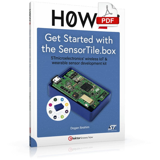
STmicroelectronics’ wireless IoT & wearable sensor development kit
‘SensorTile.box’ is a portable multi-sensor circuit board housed in a plastic box and developed by STMicroelectronics. It is equipped with a high-performance 32-bit ARM Cortex-M4 processor with DSP and FPU, and various sensor modules, such as accelerometer, gyroscope, temperature sensor, humidity sensor, atmospheric pressure sensor, microphone, and so on. SensorTile.box is ready to use with wireless IoT and Bluetooth connectivity that can easily be used with an iOS or Android compatible smartphone, regardless of the level of expertise of the users. SensorTile.box is shipped with a long-life battery and all the user has to do is connect the battery to the circuit to start using the box.
The SensorTile.box can be operated in three modes: Basic mode, Expert mode, and Pro mode. Basic mode is the easiest way of using the box since it is pre-loaded with demo apps and all the user has to do is choose the required apps and display or plot the measured data on a smartphone using an app called STE BLE Sensor. In Expert mode users can develop simple apps using a graphical wizard provided with the STE BLE Sensor. Pro mode is the most complex mode allowing users to develop programs and upload them to the SensorTile.box.
This book is an introduction to the SensorTile.box and includes the following:
Brief specifications of the SensorTile.box; description of how to install the STE BLE Sensor app on an iOS or Android compatible smartphone required to communicate with the box.
Operation of the SensorTile.box in Basic mode is described in detail by going through all of the pre-loaded demo apps, explaining how to run these apps through a smartphone.
An introduction to the Expert mode with many example apps developed and explained in detail enabling users to develop their own apps in this mode. Again, the STE BLE Sensor app is used on the smartphone to communicate with the SensorTile.box and to run the developed apps.
The book then describes in detail how to upload the sensor data to the cloud. This is an important topic since it allows the sensor measurements to be accessed from anywhere with an Internet connection, at any time.
Finally, Pro mode is described in detail where more experienced people can use the SensorTile.box to develop, debug, and test their own apps using the STM32 open development environment (STM32 ODE). The Chapter explains how to upload the developed firmware to the SensorTile.box using several methods. Additionally, the installation and use of the Unicleo-GUI package is described with reference to the SensorTile.box. This PC software package enables all of the SensorTile.box sensor measurements to be displayed or plotted in real time on the PC.
Elektor GREEN and GOLD members can download their digital edition here.
Not a member yet? Click here.
Knowledge for All!
Super Servo TesterTest Up to Four Servos Stand-Alone or In-System
Analog Signals and MicrocontrollersADCs, DACs, Current Measurement, and More
embedded world 2023
Sub-Nyquist Sampling in PracticeReliably Capturing Higher Frequencies Using Subsampling
Android Smartphone Here, ESP32 There?Practical Pproject Using the Android Wi-Fi API
Active 1-kHz Filter for Distortion MeasurementBetter Measurements Through Optimization of the Measurement Signal
Starting Out in Electronics......Multivibrating Cheerfully Further!
Err-lectronicsCorrections, Updates and Readers’ Letters
The New I3C ProtocolA Worthy Successor to I²C, or Just More Hot Air?
BlueRC: IR Remote Control with Smartphone and ESP32Adaptive and Universal
Microcontroller Documentation Explained (Part 2)Registers and Block Diagrams
Automating Test and MeasurementProgramming Test Equipment to Do What You Want
Infographics: Test and Measurement
Overvoltage Protection for Safe OperationTransient Protection for Non-Isolated DC/DC Power Modules
Wiha Measuring EquipmentReliable Electrical Testers and Meters
Automating Testing and Collaborating on Test Results
From Life’s ExperienceHigh-Level Electronics
Energy LoggerMeasuring and Recording Power Consumption
Assembling the 4tronix M.A.R.S. Rover Kit
Parking Disk with E-Paper DisplayAn Innovative Digital Replacement
eCO₂ Telegram botAir-Quality Measurement with Telegram Notification
Behind the Scenes of DIY High-End AudioElektor’s Ton Giesberts Interviewed on the Fine Art of Analog Design
HomeLab ToursWork in Progress...
RFID Tag Reading and RFID Door LockSample Projects from the Elektor Arduino Experimenting Bundle
Oscilloscope Current Probe for RFRF Current Measurements Made Easy
Not for the Faint-Hearted: Robot Arm KitWith Raspberry Pi Pico and MicroPython
Generative AIWho Made This Anyway?
Hexadoku