Dispositif de communication LoRa haute performance
L'Elecrow ThinkNode M5 est un dispositif de communication LoRa compact et portable, conçu pour la messagerie hors réseau, le partage de position et une utilisation en extérieur. Équipé d'un processeur ESP32-S3 et d'une puce LoRa SX1262, il est livré avec le micrologiciel Meshtastic préinstallé et se configure aisément via Bluetooth grâce à l'application officielle Meshtastic.
Son module multi-GNSS intégré prend en charge les systèmes GPS, GLONASS, BeiDou et QZSS pour assurer une localisation et un partage de position fiables. Les messages et les informations de l'appareil s'affichent sur un écran e-paper de 1,54 pouce économe en énergie, tandis que la batterie rechargeable intégrée de 1200 mAh permet une utilisation mobile prolongée.
Grâce à son antenne LoRa intégrée, son boîtier compact, son horloge temps réel (RTC) et sa compatibilité avec les micrologiciels Meshtastic et MeshCore, le ThinkNode M5 constitue une solution de communication pratique pour la randonnée, le camping, les zones isolées et les situations d'urgence où les réseaux mobiles conventionnels sont indisponibles.
Caractéristiques
Communication LoRa
Positionnement multi-GNSS
Batterie rechargeable de 1200 mAh
Écran à encre électronique de 1,54 pouce
Horloge en temps réel (RTC) intégrée
Compatible avec MeshCore
Compatible avec Meshtastic
Spécifications
Processeur principal (ESP32-S3)
CPU/SoC
Processeur double cœur Xtensa LX7 32 bits, cadencé jusqu'à 240 MHz
Mémoire système
512 Ko de SRAM, 8 Mo de PSRAM
Stockage
4 Mo de Flash, 384 Ko de ROM
Firmware
Entièrement compatible avec le firmware Meshtastic ; transmission du signal en mode LoRa
EPD (Écran à encre électronique)
Taille de l'écran
EPD de 1,54 pouce (écran à encre monochrome)
Technologie d'affichage
E-Ink (encre électronique)
Résolution
200 x 200
Contrôleur
SSD1681 (via interface SPI ou I²C)
Temps de rafraîchissement global
2 s
Communication sans fil
Bluetooth
Bluetooth Low Energy et Bluetooth 5.0 (configuration via smartphone)
LoRa
Module LoRa SX1262, bande EU 868 MHz (antenne externe)
Matériel
Interfaces
USB-C, RP-SMA
Fonctions
Localisation GPS (GPS, GLONASS, BeiDou, QZSS), affichage EPD, RTC, USB 2.0, gestion de l'alimentation PMU (batterie au lithium intégrée de 1200 mAh), buzzer, etc.
Boutons
Commutateur rotatif, bouton de fonction, bouton de changement de page, interrupteur GPS, bouton de réinitialisation
Indicateur LED
Alimentation, Indication GPS/LoRa
Autres
Alimentation
5 V/1 A, prise en charge de l'alimentation par USB ou batterie au lithium
Consommation électrique
Le courant de fonctionnement maximal est d'environ 340 mA (CPU + module LoRa) ; la consommation en mode basse consommation est d'environ 34 µA
Température de fonctionnement
-10 à 50°C
Température de stockage
-20 à 60°C
Humidité relative
10 à 95% à 40°C (sans condensation)
Boîtier
Plastique ABS
Dimensions
82 x 51,6 x 26,3 mm
Poids
81 g
Inclus
1x Elecrow ThinkNode M5
1x Antenne LoRa
1x Câble USB-C
1x Manuel
Téléchargements
Manual
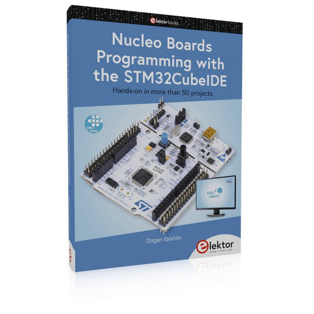
Hands-on in more than 50 projects
STM32 Nucleo family of processors are manufactured by STMicroelectronics. These are low-cost ARM microcontroller development boards. This book is about developing projects using the popular STM32CubeIDE software with the Nucleo-L476RG development board. In the early Chapters of the book the architecture of the Nucleo family is briefly described.
The book covers many projects using most features of the Nucleo-L476RG development board where the full software listings for the STM32CubeIDE are given for each project together with extensive descriptions. The projects range from simple flashing LEDs to more complex projects using modules, devices, and libraries such as GPIO, ADC, DAC, I²C, SPI, LCD, DMA, analogue inputs, power management, X-CUBE-MEMS1 library, DEBUGGING, and others. In addition, several projects are given using the popular Nucleo Expansion Boards. These Expansion Boards plug on top of the Nucleo development boards and provide sensors, relays, accelerometers, gyroscopes, Wi-Fi, and many others. Using an expansion board together with the X-CUBE-MEMS1 library simplifies the task of project development considerably.
All the projects in the book have been tested and are working. The following sub-headings are given for each project: Project Title, Description, Aim, Block Diagram, Circuit Diagram, and Program Listing for the STM32CubeIDE.
In this book you will learn about
STM32 microcontroller architecture;
the Nucleo-L476RG development board in projects using the STM32CubeIDE integrated software development tool;
external and internal interrupts and DMA;
DEBUG, a program developed using the STM32CubeIDE;
the MCU in Sleep, Stop, and in Standby modes;
Nucleo Expansion Boards with the Nucleo development boards.
What you need
a PC with Internet connection and a USB port;
STM32CubeIDE software (available at STMicroelectronics website free of charge)
the project source files, available from the book’s webpage hosted by Elektor;
Nucleo-L476RG development board;
simple electronic devices such as LEDs, temperature sensor, I²C and SPI chips, and a few more;
Nucleo Expansion Boards (optional).
Ce cours complet de programmation de microcontrôleurs basé sur l’Arduino Uno comprend un manuel, un kit de composants, des projets pratiques ainsi qu’un cours en ligne complet avec simulations. Il est idéal pour apprendre pas à pas la programmation des systèmes embarqués avec Arduino grâce à une approche pratique.
Une introduction pratique aux systèmes embarqués avec l’Arduino Uno
Ce cours s’adresse aux débutants en systèmes embarqués recherchant une approche structurée et basée sur des exemples.
Un kit de composants comprenant des LED et des résistances, des interrupteurs, des capteurs et actionneurs, des afficheurs, une breadboard et des fils est inclus. Ceux-ci sont utilisés dans le cours pour illustrer des applications concrètes.
Aucune expérience préalable avec Arduino ou le développement embarqué n’est requise. Chaque section propose des exemples pratiques et des mini-projets conçus pour renforcer les concepts clés et encourager l’exploration. À la fin du cours, vous serez capable non seulement de reproduire les exemples, mais aussi de développer vos propres idées et applications.
Que allez-vous apprendre ?
Programmation de microcontrôleurs avec Arduino en utilisant la carte Uno R3
Utilisation des entrées/sorties numériques, lecture de boutons et encodeurs, commande de LED et relais
Lecture des entrées analogiques, tensions et capteurs analogiques
Génération de signaux analogiques et PWM
Utilisation des communications série comme UART, I²C et SPI pour piloter des afficheurs et lire des capteurs numériques et cartes SD
Gestion du temps
Utilisation des interruptions
Entrées capteurs en temps réel et contrôle via boutons, LED et afficheurs
Commande d’actionneurs comme relais et servomoteurs
À qui s’adresse ce cours ?
Étudiants et autodidactes explorant les systèmes embarqués
Makers et passionnés d’IoT souhaitant améliorer leurs compétences en hardware
Formateurs et enseignants à la recherche de matériel pédagogique prêt à l’emploi
Contenu de la boîte
Accès au cours complet sur la plateforme Elektor Academy Pro
Carte microcontrôleur Uno R3 + câble USB
Livre : Programming Microcontrollers in C/C++ Using Arduino
Fichiers de projet téléchargeables pour chaque module
Boîte de composants :
2× LED, rouge, 5 mm
LED, verte, 5 mm
3× résistance, 470 Ω, 0,25 W
LDR
Potentiomètre, 10 kΩ, linéaire
Bouton-poussoir
Module encodeur rotatif
Module relais
Capteur DHT22 (température & humidité)
Afficheur 7 segments 4 digits compatible TM1637
MPU-6050 IMU avec connecteurs
Afficheur OLED I²C compatible SSD1306
Adaptateur carte micro SD avec connecteur
Buzzer
Micro servo SG90
Écran TFT SPI 240×320 compatible ILI9341
20× fils jumper
Breadboard
Tous les cours de programmation (et différences de contenu)
Cours
Arduino
Raspberry Pi Pico with Arduino C/C++
ESP32 with Arduino C/C++
Raspberry Pi Pico with MicroPython
ESP32 with MicroPython
Cours en ligne
Access to Arduino Course
Access to Pico with Arduino C/C++ Course
Access to ESP32 with Arduino C/C++ Course
Access to Pico with MicroPython Course
Access to ESP32 with MicroPython Course
Carte
Uno R3
Raspberry Pi Pico
ESP32
Raspberry Pi Pico
ESP32
Livre
Programming Microcontrollers in C/C++ Using Arduino
Programming Microcontrollers in C/C++ Using Arduino
Programming Microcontrollers in C/C++ Using Arduino
Programming Microcontrollers in MicroPython
Programming Microcontrollers in MicroPython
Kit
Boîte de composants (40 pièces)
Boîte de composants (40 pièces)
Boîte de composants (40 pièces)
Boîte de composants (40 pièces)
Boîte de composants (40 pièces)
Diese Ausgabe steht allen GOLD- und GREEN-Mitgliedern auf der ElektorMagazine-Website zum Download bereit!
Sie sind noch kein Mitglied? Hier klicken!
Ein autonomer SensorknotenLoRa-Datenübertragung und Solar-Stromversorgung
Elektor eXpansion Board v1.0Für ESP32-S3 und andere XIAO-Controller-Boards
Modelleisenbahn mit KameraEinbau eines ESP32-CAM-Moduls
Breitband-Magnetantenne für LangwelleMehrere Sender ohne Abstimmung
TensorFlow Lite auf kleinen MikrocontrollernEin (sehr) einsteigerfreundlicher Blickwinkel
Ein Hub für RS-422 und RS-485Verdrahten Sie Ihre Geräte wie einen Stern
HF-SondeMit LED-Balkenanzeige
Aller Anfang...muss nicht schwer sein: mehr Verstärkerschaltungen
MultiLayer-SegmentierungEin neuer Ansatz für adressierbare LED-Streifen
Open VarioOpen-Source Multifunktions-Variometer für Gleitschirmflieger
Aus dem Leben gegriffenÜber die Selbstverständlichkeit der Dinge
KI-gestützter WasserzählerTeil 2: Firmware-Installation, Anwendung und Montage
Intelligente LandwirtschaftML-basierte Schädlingserkennung mit IoT-Vernetzung
Warum Anybus CompactCom die ideale Wahl für die industrielle Embedded-Kommunikation ist
Kommunikationsstandard IQRFZuverlässigkeit für verlustbehaftete drahtlose Mesh-Netzwerke mit niedriger Rate
Bau eines intelligenten AgrarrobotersWelche wesentlichen technischen Überlegungen und Herausforderungen müssen Entwickler von Agrarrobotern berücksichtigen?
Audio-Notchfilter mit einstellbarer FrequenzUniverselle Lösung zur Unterdrückung von Frequenzen im Audiobereich
Das System LeoINAGPSNützliche Einblicke in Ihr Elektrofahrzeug
Solarbetriebener LoRa-KnotenEine modulare, kompakte und vielseitige IoT-Lösung
AWS für Arduino und Co.Teil 2: Daten senden mit AWS-IoT-ExpressLink
Projekt 2.0Korrekturen, Updates und Leserbriefe
2024: Eine Odyssee in die KIBeschleuniger: Desktop vs. Embedded, ein Blick auf einige Optionen
ESP32-ReichweitenverlängererEine einfache Antennenmodifikation
Umfassendes Buch-Hardware-Bundle für den RP2040-Mikrocontroller mit über 80 Projekten
Entdecken Sie in diesem Bundle das Potenzial der modernen Controller-Technologie mit dem Raspberry Pi Pico. Das leicht verständliche Handbuch eignet sich sowohl für Anfänger als auch für erfahrene Benutzer und führt Sie von den Grundlagen der Elektronik bis hin zu den komplexen Aspekten der digitalen Signalverarbeitung. Mit dem Raspberry Pi Pico, dem speziellen Hardware-Kit und der MicroPython-Programmierung lernen Sie die wichtigsten Prinzipien des Schaltungsdesigns, der Datenerfassung und -verarbeitung.
Machen Sie praktische Erfahrungen mit über 80 Projekten wie einer Stoppuhr mit OLED-Display, einem Laser-Entfernungsmesser und einem servogesteuerten Lüfter. Diese Projekte sollen Ihnen helfen, das Gelernte in realen Szenarien anzuwenden. Das Buch behandelt auch fortgeschrittene Themen wie drahtlose RFID-Technologie, Objekterkennung und Sensorintegration für die Robotik.
Ganz gleich, ob Sie Ihre Kenntnisse in der Elektronik erweitern oder tiefer in eingebettete Systeme eintauchen möchten, dieses Bundle ist die perfekte Ressource, um das volle Potenzial des Raspberry Pi Pico zu erkunden.
Inhalt des Bundles
1x Projektbuch (287 Seiten)
1x Smart Car Kit
Bauteile
2x Lötfreies Steckbrett (400 Löcher)
1x Lötfreies Steckbrett (170 Löcher)
5x bunte 5-mm-LEDs (Grün, Rot, Blau, Gelb und Weiß)
1x Lasersender
1x Passiver Summer
1x Micro-USB-Kabel (30 cm)
1x 65 Überbrückungskabel
1x 20 cm männlicher auf weiblicher Dupont-Draht
1x Transparentes Gehäuse
1x Magnet (Durchmesser: 8 mm, Dicke: 5 mm)
1x Drehpotentiometer
10x 2 KΩ Widerstände
2x M2, 5x30 mm Kupfersäulen
10x Kreuzschlitz-Flachkopfschrauben
10x M2,5 Sechskantmuttern aus Nickel
1x 2-Zoll-Mehrzweckschraubendreher
Module
1x RGB-Modul
1x 9G-Servo
1x Dual-Achsen-XY-Joystick-Modul
1x RC522 RFID-Modul
1x 4-Bit-Digital-LED-Display-Modul
1x Ampel-Anzeigemodul
1x Drehgebermodul
1x 1602 LCD-Anzeigemodul (blau)
1x Fotowiderstandsmodul
1x Gleichstrommotor mit männlichem Dupont-Kabel
1x Lüfterflügel
1x Regentropfen-Modul
1x OLED-Modul
1x Membranschalter-Tastatur
1x Mini-Magnetfedermodul
1x Infrarot-Fernbedienung
1x Infrarot-Empfängermodul
1x DC-Schrittmotor-Treiberplatine
1x Button
Sensoren
1x Vibrationssensor
1x Bodenfeuchtesensor
1x Schallsensor
1x Mini-PIR-Bewegungssensor
1x Temperatur & Feuchtigkeitssensor
1x Flammensensor
2x Crash-Sensor
2x Tracking-Sensor
1x Ultraschallsensor
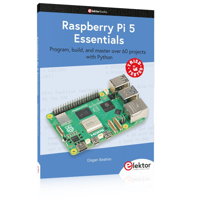
Program, build, and master over 60 projects with Python
The Raspberry Pi 5 is the latest single-board computer from the Raspberry Pi Foundation. It can be used in many applications, such as in audio and video media centers, as a desktop computer, in industrial controllers, robotics, and in many domestic and commercial applications. In addition to the well-established features found in other Raspberry Pi computers, the Raspberry Pi 5 offers Wi-Fi and Bluetooth (classic and BLE), which makes it a perfect match for IoT as well as in remote and Internet-based control and monitoring applications. It is now possible to develop many real-time projects such as audio digital signal processing, real-time digital filtering, real-time digital control and monitoring, and many other real-time operations using this tiny powerhouse.
The book starts with an introduction to the Raspberry Pi 5 computer and covers the important topics of accessing the computer locally and remotely. Use of the console language commands as well as accessing and using the desktop GUI are described with working examples. The remaining parts of the book cover many Raspberry Pi 5-based hardware projects using components and devices such as
LEDs and buzzers
LCDs
Ultrasonic sensors
Temperature and atmospheric pressure sensors
The Sense HAT
Camera modules
Example projects are given using Wi-Fi and Bluetooth modules to send and receive data from smartphones and PCs, and sending real-time temperature and atmospheric pressure data to the cloud.
All projects given in the book have been fully tested for correct operation. Only basic programming and electronics experience are required to follow the projects. Brief descriptions, block diagrams, detailed circuit diagrams, and full Python program listings are given for all projects described.
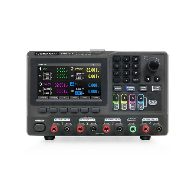
The Siglent SPD4121X is a 4-channel DC Linear Programmable Power Supply equipped with a 4.3-inch TFT-LCD display, friendly human-machine interface, and excellent performance indicators. Real-time waveform display provides engineers with an informative user interface.
SPD4121X offers a total output power of 285 W with a resolution of 1 mV/1 mA. The maximum voltage and current for each channel are as follows:
CH1: 15 V/1.5 A
CH2: 12 V/10 A
CH3: 12 V/10 A
CH4: 15 V/1.5 A
Caractéristiques
Rated output power: 285 W
Rated voltage: 32 V, 12 V, 30 V
Up to four high-precision power supplies with independent controllable outputs, supporting CH2 and CH3 series and parallel connections
Clear graphical interface with waveform and timer display modes
5-digit voltage and current display with minimum resolution of 1 mV, 1 mA
Fast output response time: <50us
The high current channel support remote voltage compensation sense function. The maximum compensation voltage is 0.6 V
Overvoltage protection and overcurrent protection or safe and accurate operation
Equipped with a 4.3-inch TFT-LCD display (480 x 272 resolution)
USB and LAN standard communication
USB-GPIB module is optional
Excellent channel density with up to 4 channels in a 3U half rack package
Internal data storage for setups and parameters
Embedded Web Server with instrument communication that doesn’t require software installation
Fully SCPI programming command set support as well as a LabView driver for remote control and system automation
Spécifications
SPD4323X
SPD4121X
SPD4306X
Channel Output
CH1: Voltage 0 to 6 V Current 0 to 3.2 ACH2: Voltage 0 to 32 V Current 0 to 3.2 ACH3: Voltage 0 to 32 V Current 0 to 3.2 ACH4: Voltage 0 to 6 V Current 0 to 3.2 A
CH1: Voltage 0 to 15 V Current 0 to 1.5 ACH2: Voltage 0 to 12 V Current 0 to 10 ACH3: Voltage 0 to 12 V Current 0 to 10 ACH4: Voltage 0 to 15 V Current 0 to 1.5 A
CH1: Voltage 0 to 15 V Current 0 to 1.5 ACH2: Voltage 0 to 30 V Current 0 to 6 ACH3: Voltage 0 to 30 V Current 0 to 6 ACH4: Voltage 0 to 15 V Current 0 to 1 A
Resolution
1 mV, 1 mA
1 mV, 1 mA
1 mV, 1 mA
Setting Accuracy
Voltage: ±(0.03% of reading+10) mV, Current: ±(0.3% of reading+10) mA
Voltage: ±(0.03% of reading+10) mV, Current: ±(0.3% of reading+10) mA
Voltage: ±(0.03% of reading+10) mV, Current: ±(0.3% of reading+10) mA
Readback Accuracy
Voltage: ±(0.03% of reading+10) mV, Current: ±(0.3% of reading+10) mA
Voltage: ±(0.03% of reading+10) mV, Current: ±(0.3% of reading+10) mA
Voltage: ±(0.03% of reading+10) mV, Current: ±(0.3% of reading+10) mA
Display
4.3" TFT-LCD 5-digit voltage and current display
4.3" TFT-LCD 5-digit voltage and current display
4.3" TFT-LCD 5-digit voltage and current display
Output power
240 W
285 W
400 W
Inclus
1x Siglent SPD4121X Power Supply
1x Power cord (EU)
1x Output test cord (3 A)
1x USB cable
1x Quick start guide
Téléchargements
Datasheet
Manual
Quick start
Le MDP-P906 dispose d'un ventilateur de refroidissement intégré et d'une puissance de sortie maximale de 300 W, ce qui permet de répondre à un plus grand nombre de besoins en matière de tests et d'applications. Grâce à la communication sans fil 2,4 GHz, il peut être connecté au module MDP-M01 Smart Digital Monitor pour réaliser la combinaison libre de plusieurs canaux de 300 W par canal. Le MDP-P906 possède une stabilité et une fiabilité comparables à ceux d'une alimentation professionnelle. Il peut délivrer un courant constant et il offre des fonctions puissantes telles que la sortie programmable, la sortie temporelle, le contrôle temporel, la compensation automatique, le mode boost, etc., ce qui en fait un véritable bloc d'alimentation CC linéaire programmable, intelligent et personnalisé. Le MDP-P906 adopte une coque en alliage d'aluminium usinée avec précision par CNC, avec une finition soignée, un aspect nouveau, miniature et esthétique, il renverse complètement l'image rigide de l'alimentation de bureau traditionnelle. Grâce à sa conception modulaire empilable et à sa fonction de communication sans fil, le MDP-P906 peut fonctionner indépendamment ou en binôme, à la fois sur l'établi et pour la maintenance sur site. Le MDP-P906 est une solution parfaite pour les ingénieurs en électronique, en particulier les ingénieurs d'application sur le terrain, afin de répondre aux différents besoins en matière de sources d'alimentation. Ventilateur silencieux intégré, refroidissement instantané, assurant une sortie stable et efficace ! Compensation linéaire intelligente, tension et courant constants Sortie positive et négative, boost en série, partage du courant en parallèle Applications Tests universels et expériences pédagogiques en laboratoire de R&D Maintenance des produits numériques Vérification des propriétés et diagnostic des défauts des appareils et des circuits Alimentation de secours pour les modèles réduits d'avions et de véhicules Test d'alimentation de circuits ou de modules RF et micro-ondes Contrôle et inspection de la qualité Alimentation purifiée de circuits hybrides numériques-analogiques de haute précision et d'appareils audio Hi-Fi Specifications Entrée CC 4,2-30 V/14 A (Max) QC 3.0/PD2.0, 20 V/5 A (Max) Sortie 0-30 V/0-10 A, 300 W (Max) Efficacité de la conversion 95% Résolution de la sortie 10 mV/2 mA, jusqu'à 1 mV/1 mA via le module de contrôle de l'affichage Précision de la sortie 0,03%+5 mV0,05%+2 mV Taux d’ajustement Taux d'ajustement de la charge Taux d'ajustement de la puissance Ondulation et bruit rms, 3 mVpp ; 2 mArms Réponse transitoire Protections de sécurité Protection contre les surtensions d'entrée, les sous-tensions et les inversions de connexion, surintensité de sortie, protection contre les retours d'eau et protection contre la surchauffe Autres Arrêt automatique et passage en mode micro-alimentationPrise en charge de la mise à jour du micrologiciel par USB Dimensions 112 x 66 x 20 mm Poids 181 g Inclus 1x Alimentation numérique MDP-P906 2x Câble de sortie 1x Manuel de l'utilisateur Téléchargements User Manual v1.1 Firmware v1.32
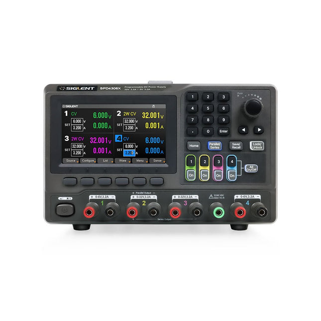
The Siglent SPD4306X is a 4-channel DC Linear Programmable Power Supply equipped with a 4.3-inch TFT-LCD display, friendly human-machine interface, and excellent performance indicators. Real-time waveform display provides engineers with an informative user interface.
SPD4306X offers a total output power of 400 W with a resolution of 1 mV/1 mA. The maximum voltage and current for each channel are as follows:
CH1: 15 V/1.5 A
CH2: 30 V/6 A
CH3: 30 V/6 A
CH4: 15 V/1 A
Caractéristiques
Rated output power: 400 W
Rated voltage: 32 V, 12 V, 30 V
Up to four high-precision power supplies with independent controllable outputs, supporting CH2 and CH3 series and parallel connections
Clear graphical interface with waveform and timer display modes
5-digit voltage and current display with minimum resolution of 1 mV, 1 mA
Fast output response time: <50us
The high current channel support remote voltage compensation sense function. The maximum compensation voltage is 0.6 V
Overvoltage protection and overcurrent protection or safe and accurate operation
Equipped with a 4.3-inch TFT-LCD display (480 x 272 resolution)
USB and LAN standard communication
USB-GPIB module is optional
Excellent channel density with up to 4 channels in a 3U half rack package
Internal data storage for setups and parameters
Embedded Web Server with instrument communication that doesn’t require software installation
Fully SCPI programming command set support as well as a LabView driver for remote control and system automation
Spécifications
SPD4323X
SPD4121X
SPD4306X
Channel Output
CH1: Voltage 0 to 6 V Current 0 to 3.2 ACH2: Voltage 0 to 32 V Current 0 to 3.2 ACH3: Voltage 0 to 32 V Current 0 to 3.2 ACH4: Voltage 0 to 6 V Current 0 to 3.2 A
CH1: Voltage 0 to 15 V Current 0 to 1.5 ACH2: Voltage 0 to 12 V Current 0 to 10 ACH3: Voltage 0 to 12 V Current 0 to 10 ACH4: Voltage 0 to 15 V Current 0 to 1.5 A
CH1: Voltage 0 to 15 V Current 0 to 1.5 ACH2: Voltage 0 to 30 V Current 0 to 6 ACH3: Voltage 0 to 30 V Current 0 to 6 ACH4: Voltage 0 to 15 V Current 0 to 1 A
Resolution
1 mV, 1 mA
1 mV, 1 mA
1 mV, 1 mA
Setting Accuracy
Voltage: ±(0.03% of reading+10) mV, Current: ±(0.3% of reading+10) mA
Voltage: ±(0.03% of reading+10) mV, Current: ±(0.3% of reading+10) mA
Voltage: ±(0.03% of reading+10) mV, Current: ±(0.3% of reading+10) mA
Readback Accuracy
Voltage: ±(0.03% of reading+10) mV, Current: ±(0.3% of reading+10) mA
Voltage: ±(0.03% of reading+10) mV, Current: ±(0.3% of reading+10) mA
Voltage: ±(0.03% of reading+10) mV, Current: ±(0.3% of reading+10) mA
Display
4.3" TFT-LCD 5-digit voltage and current display
4.3" TFT-LCD 5-digit voltage and current display
4.3" TFT-LCD 5-digit voltage and current display
Output power
240 W
285 W
400 W
Inclus
1x Siglent SPD4306X Power Supply
1x Power cord (EU)
1x Output test cord (3 A)
1x USB cable
1x Quick start guide
Téléchargements
Datasheet
Manual
Quick start
Points forts
Fréquence de sortie (sinusoïdale) : 50 MHz
Fréquence de sortie (carré) : 15 MHz
Canaux : 2
Longueur de forme d'onde arbitraire : 16 Mpts
Caractéristiques
Technologie unique SiFi II (Signal Fidelity II) : génère les formes d'onde arbitraires point par point ; récupérer le signal sans distorsion ; taux d'échantillonnage précis et réglable ; gigue de toutes les formes d'onde de sortie (y compris sinusoïdale, impulsionnelle, etc.) aussi faible que 200 ps
Profondeur de mémoire de 16 Mpts par canal pour les formes d'onde arbitraires
Double canal standard avec les mêmes performances, équivalent à deux sources de signaux indépendantes
Stabilité haute fréquence : ±1 ppm ; faible bruit de phase : -105 dBc/Hz
Générateur d'harmoniques d'ordre élevé intégré (au maximum des harmoniques d'ordre 8)
Compteur de fréquence complet intégré à 7 chiffres/s, bande passante de 240 MHz
Jusqu'à 160 formes d'onde arbitraires intégrées, couvrant les signaux courants dans les applications d'ingénierie, l'électronique médicale, l'électronique automobile, le traitement mathématique et d'autres domaines divers
Taux d'échantillonnage jusqu'à 250 MSa/s, résolution verticale 16 bits
Fonction d'édition de séquence de forme d'onde arbitraire disponible ; des formes d'onde arbitraires peuvent également être générées via le logiciel PC
Diverses fonctions de modulation analogiques et numériques : AM, FM, PM, ASK, FSK, PSK et PWM.
Fonction de combinaison de formes d'onde standard, capable de produire des formes d'onde spécifiées combinées avec les formes d'onde de base
Fonction de suivi de canal standard, lorsqu'elle est activée, tous les paramètres des deux canaux sont mis à jour en fonction des configurations des utilisateurs
Interface standard : hôte et périphérique USB et LAN (appareil LXI Core 2011) ; Fonction USB GPIB prise en charge
Écran TFT 4,3''
Inclus
1x Rigol DG2052 Fonction/Générateur de forme d'onde arbitraire
1x Cordon d'alimentation
1x Câble USB
Ce cours complet de programmation de microcontrôleurs basé sur le Raspberry Pi Pico comprend un manuel, un kit de composants, des projets pratiques ainsi qu’un cours en ligne complet avec simulations. Il est idéal pour apprendre pas à pas la programmation des systèmes embarqués avec Arduino grâce à une approche pratique.
Une introduction pratique aux systèmes embarqués avec le Raspberry Pi Pico
Ce cours s’adresse aux débutants en systèmes embarqués recherchant une approche structurée et basée sur des exemples.
Un kit de composants comprenant des LED et des résistances, des interrupteurs, des capteurs et actionneurs, des afficheurs, une breadboard et des fils est inclus. Ceux-ci sont utilisés dans le cours pour illustrer des applications concrètes.
Aucune expérience préalable avec Arduino ou le développement embarqué n’est requise. Chaque section propose des exemples pratiques et des mini-projets conçus pour renforcer les concepts clés et encourager l’exploration. À la fin du cours, vous serez capable non seulement de reproduire les exemples, mais aussi de développer vos propres idées et applications.
Que allez-vous apprendre ?
Programmation de microcontrôleurs en C/C++ avec le Raspberry Pi Pico via l’IDE Arduino
Utilisation des entrées/sorties numériques, lecture de boutons et encodeurs, commande de LED et relais
Lecture des entrées analogiques, tensions et capteurs analogiques
Génération de signaux analogiques et PWM
Utilisation des communications série comme UART, I²C et SPI pour piloter des afficheurs et lire des capteurs numériques et cartes SD
Gestion du temps
Utilisation des interruptions
Entrées capteurs en temps réel et contrôle via boutons, LED et afficheurs
Commande d’actionneurs comme relais et servomoteurs
À qui s’adresse ce cours ?
Étudiants et autodidactes explorant les systèmes embarqués
Makers et passionnés d’IoT souhaitant améliorer leurs compétences en hardware
Formateurs et enseignants à la recherche de matériel pédagogique prêt à l’emploi
Contenu de la boîte
Accès au cours complet sur la plateforme Elektor Academy Pro
Carte microcontrôleur Raspberry Pi Pico + câble USB
Livre : Programming Microcontrollers in C/C++ Using Arduino
Fichiers de projet téléchargeables pour chaque module
Boîte de composants :
2× LED, rouge, 5 mm
LED, verte, 5 mm
3× résistance, 470 Ω, 0,25 W
LDR
Potentiomètre, 10 kΩ, linéaire
Bouton-poussoir
Module encodeur rotatif
Module relais
Capteur DHT22 (température & humidité)
Afficheur 7 segments 4 digits compatible TM1637
MPU-6050 IMU avec connecteurs
Afficheur OLED I²C compatible SSD1306
Adaptateur carte micro SD avec connecteur
Buzzer
Micro servo SG90
Écran TFT SPI 240×320 compatible ILI9341
20× fils jumper
Breadboard
Tous les cours de programmation (et différences de contenu)
Cours
Arduino
Raspberry Pi Pico with Arduino C/C++
ESP32 with Arduino C/C++
Raspberry Pi Pico with MicroPython
ESP32 with MicroPython
Cours en ligne
Access to Arduino Course
Access to Pico with Arduino C/C++ Course
Access to ESP32 with Arduino C/C++ Course
Access to Pico with MicroPython Course
Access to ESP32 with MicroPython Course
Carte
Uno R3
Raspberry Pi Pico
ESP32
Raspberry Pi Pico
ESP32
Livre
Programming Microcontrollers in C/C++ Using Arduino
Programming Microcontrollers in C/C++ Using Arduino
Programming Microcontrollers in C/C++ Using Arduino
Programming Microcontrollers in MicroPython
Programming Microcontrollers in MicroPython
Kit
Boîte de composants (40 pièces)
Boîte de composants (40 pièces)
Boîte de composants (40 pièces)
Boîte de composants (40 pièces)
Boîte de composants (40 pièces)
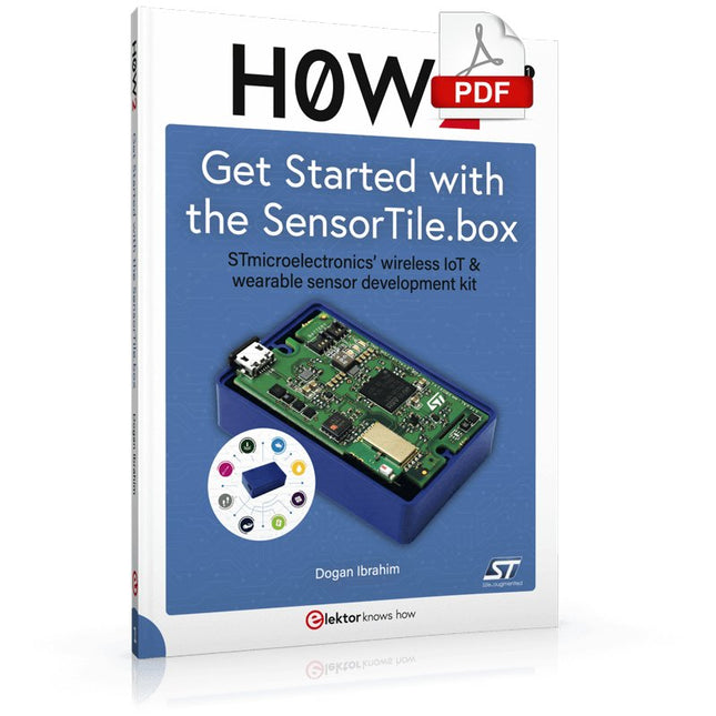
STmicroelectronics’ wireless IoT & wearable sensor development kit
‘SensorTile.box’ is a portable multi-sensor circuit board housed in a plastic box and developed by STMicroelectronics. It is equipped with a high-performance 32-bit ARM Cortex-M4 processor with DSP and FPU, and various sensor modules, such as accelerometer, gyroscope, temperature sensor, humidity sensor, atmospheric pressure sensor, microphone, and so on. SensorTile.box is ready to use with wireless IoT and Bluetooth connectivity that can easily be used with an iOS or Android compatible smartphone, regardless of the level of expertise of the users. SensorTile.box is shipped with a long-life battery and all the user has to do is connect the battery to the circuit to start using the box.
The SensorTile.box can be operated in three modes: Basic mode, Expert mode, and Pro mode. Basic mode is the easiest way of using the box since it is pre-loaded with demo apps and all the user has to do is choose the required apps and display or plot the measured data on a smartphone using an app called STE BLE Sensor. In Expert mode users can develop simple apps using a graphical wizard provided with the STE BLE Sensor. Pro mode is the most complex mode allowing users to develop programs and upload them to the SensorTile.box.
This book is an introduction to the SensorTile.box and includes the following:
Brief specifications of the SensorTile.box; description of how to install the STE BLE Sensor app on an iOS or Android compatible smartphone required to communicate with the box.
Operation of the SensorTile.box in Basic mode is described in detail by going through all of the pre-loaded demo apps, explaining how to run these apps through a smartphone.
An introduction to the Expert mode with many example apps developed and explained in detail enabling users to develop their own apps in this mode. Again, the STE BLE Sensor app is used on the smartphone to communicate with the SensorTile.box and to run the developed apps.
The book then describes in detail how to upload the sensor data to the cloud. This is an important topic since it allows the sensor measurements to be accessed from anywhere with an Internet connection, at any time.
Finally, Pro mode is described in detail where more experienced people can use the SensorTile.box to develop, debug, and test their own apps using the STM32 open development environment (STM32 ODE). The Chapter explains how to upload the developed firmware to the SensorTile.box using several methods. Additionally, the installation and use of the Unicleo-GUI package is described with reference to the SensorTile.box. This PC software package enables all of the SensorTile.box sensor measurements to be displayed or plotted in real time on the PC.