Pfiffige Lösungen mit Arduino Pro Mini und ATmega328-Boards
Mit einem einfachen Arduino Pro Mini Board und ein paar weiteren Bauteilen lassen sich heute für wenig Geld Projekte realisieren, die vor 20 oder 30 Jahren noch undenkbar waren oder ein kleines Vermögen gekostet hätten. Von einfachen LED-Effekten bis zur Ladestation – die den Akku auf Herz und Nieren prüft – ist in diesem Buch vieles dabei.
Als Mikrocontroller dient bei allen beschriebenen Projekten der ATmega328, der mit seinen 20 Ein- und Ausgangsleitungen unzählige Möglichkeiten zum Messen, Schalten und Steuern bietet. Mit einem 7-Segment-Display und ein paar Widerständen lässt sich daraus z. B. ein Voltmeter bauen oder mittels NTC ein Thermometer. Die Arduino-Plattform bietet dabei die perfekte Entwicklungsumgebung zum Programmieren der Boards.
Neben den ganz konkreten Projekten soll das Buch aber auch das nötige Wissen vermitteln, um eigene Ideen zu realisieren. Wie misst man was? Welches ist der geeignete Transistor, um verschiedene Verbraucher zu schalten? Wann ist man mit einem IC besser bedient, oder wie schaltet man Netzspannung? Auch batteriebetriebene Projekte mit LilyPad sind ausführlich thematisiert. Ebenso vielerlei Motoren, vom einfachen Gleichstrommotor bis zum Schrittmotor.
Sensoren sind ein weiteres spannendes Thema. Nur zwei Beispiele: Mit einem winzigen Bauteil lässt sich tatsächlich messen, dass der Luftdruck am Fußboden höher ist als auf Tischhöhe. Mit einem simplen Infrarot-Empfänger kann man ausgedienten Fernbedienungen ein zweites Leben schenken und die Wohnung damit steuern.
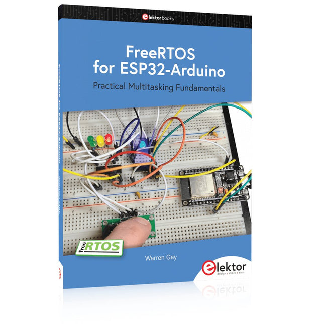
Practical Multitasking Fundamentals
Programming embedded systems is difficult because of resource constraints and limited debugging facilities. Why develop your own Real-Time Operating System (RTOS) as well as your application when the proven FreeRTOS software is freely available? Why not start with a validated foundation?
Every software developer knows that you must divide a difficult problem into smaller ones to conquer it. Using separate preemptive tasks and FreeRTOS communication mechanisms, a clean separation of functions is achieved within the entire application. This results in safe and maintainable designs.
Practicing engineers and students alike can use this book and the ESP32 Arduino environment to wade into FreeRTOS concepts at a comfortable pace. The well-organized text enables you to master each concept before starting the next chapter. Practical breadboard experiments and schematics are included to bring the lessons home. Experience is the best teacher.
Each chapter includes exercises to test your knowledge. The coverage of the FreeRTOS Application Programming Interface (API) is complete for the ESP32 Arduino environment. You can apply what you learn to other FreeRTOS environments, including Espressif’s ESP-IDF. The source code is available from GitHub. All of these resources put you in the driver’s seat when it is time to develop your next uber-cool ESP32 project.
What you will learn:
How preemptive scheduling works within FreeRTOS
The Arduino startup “loopTask”
Message queues
FreeRTOS timers and the IDLE task
The semaphore, mutex, and their differences
The mailbox and its application
Real-time task priorities and its effect
Interrupt interaction and use with FreeRTOS
Queue sets
Notifying tasks with events
Event groups
Critical sections
Task local storage
The gatekeeper task
Le LCR-mètre haute précision FNIRSI LC1020E avec testeur ESR est une solution portable et intelligente pour tester les composants électroniques, offrant une précision de base allant jusqu'à 0,3%. Il est idéal pour les ingénieurs, les techniciens et les makers. L'appareil prend en charge les mesures L/Q, C/D et R/D à l'aide de modèles de circuits équivalents en série et en parallèle, et dispose d'un écran couleur TFT de 2,8 pouces.
Grâce à ses seuils préréglés et à ses alertes audiovisuelles, il permet une évaluation rapide de la conformité, ce qui le rend parfait pour les tests par lots et le contrôle qualité. Prenant en charge des fréquences de test allant jusqu'à 100 kHz, il est parfaitement adapté à l'analyse haute fréquence des inductances, des condensateurs et des résistances.
Caractéristiques
Précision de ±0,05% avec une résolution de 4,5 chiffres
Identification automatique des composants R/L/C pour des mesures rapides
5 fréquences de test (100 Hz–100 kHz) et 3 niveaux de tension (0,1–0,6 V)
Double affichage : L/C/R/Z + X/D/Q/θ/ESR
Mode de tri et tension de polarisation pour les tests par lots
Double port (3/5 bornes) avec prise en charge Kelvin à 4 fils
Maintien et enregistrement des données pour un flux de travail efficace
Compact, rechargeable (3000 mAh) – idéal pour une utilisation en laboratoire et sur le terrain
Spécifications
Généralités
Fréquences de test
100 Hz, 120 Hz, 1 kHz, 10 kHz, 100 kHz
Précision de base
0,3%
Affichage
Écran LCD TFT 2,8 pouces
Chiffres d'affichage
Paramètre principal : 4,5 chiffres
Paramètre secondaire : 4,5 chiffres
Paramètres de mesure
Paramètres principaux : AUTO/R/C/L/Z
Paramètres secondaires : X/D/Q/θ/ESR
Plage de mesure
L : 0-100 H
C : 0-100 mF
R : 0-10 M
Biais interne
0,0 V, 0,5 V
Niveau de test
0,1 V, 0,3 V, 0,6 V
Fonctions d'étalonnage
Étalonnage en circuit ouvert, étalonnage en court-circuit
Fonction de comparaison
Permet de calculer l'erreur relative entre la valeur de mesure du composant et la valeur nominale, affichée en pourcentage, et fournit des résultats filtrés. Les valeurs nominales et la tolérance peuvent être définies, la plage de tolérance étant réglable de 0,1% à 99,9%
Enregistrement des fonctions
Vérifie si les données mesurées du composant correspondent à la valeur nominale et à la tolérance définies, en enregistrant le nombre de mesures réussies et échouées
Configuration des bornes de test
Trois bornes, cinq bornes
Impédance de sortie
100 Ω
Interface
USB-C (port série virtuel)
Autres
Paramètres de langue, luminosité de l'écran, paramètres audio, mise hors tension automatique, paramètres de calibrage, informations système
Batterie
Batterie au lithium de 3000 mAh
Dimensions
18,5 x 8,5 x 3,5 cm
Poids
680 g
Capacité (C)
Plage : 1mF-100mF
100 Hz : 5% ±5 chiffres
1 kHz : 3% ±5 chiffres
10 kHz : /
100 kHz : /
Plage : 1uF-1mF
100 Hz : 1% ±4 chiffres
1 kHz : 0,5% ±5 chiffres
10 kHz : 2% ±5 chiffres
100 kHz : 3% ±4 chiffres
Plage : 1nF-1uF
100 Hz : /
1 kHz : 0,3% ±2 chiffres
10 kHz : 0,4% ±2 chiffres
100 kHz : 1% ±4 chiffres
Plage : 1pF-1nF
100 Hz : /
1 kHz : 2% ±2 chiffres
10 kHz : 1,5% ±2 chiffres
100 kHz : 2% ±4 chiffres
Inductance (L)
Plage : 1H-100H
100 Hz : 2% ±5 chiffres
1 kHz : 2% ±5 chiffres
10 kHz : /
100 kHz : /
Plage : 1mH-1H
100 Hz : 0,4% ±5 chiffres
1 kHz : 0,3% ±2 chiffres
10 kHz : 0,4% ±3 chiffres
100 kHz : 2,5% ±5 chiffres
Plage : 10uH-1mH
100 Hz : 3% ±5 chiffres
1 kHz : 0,5% ±4 chiffres
10 kHz : 0,5% ±3 chiffres
100 kHz : 1,5% ±5 chiffres
Plage : 1uH-10uH
100 Hz : /
1 kHz : 2% ±5 chiffres
10 kHz : 2% ±5 chiffres
100 kHz : 4% ±5 chiffres
Résistance (R)
Plage : 1MΩ-10MΩ
100 Hz : 5% ±4 chiffres
1 kHz : 3% ±3 chiffres
10 kHz : /
100 kHz : /
Plage : 1KΩ-1MΩ
100 Hz : 0,4% ±4 chiffres
1 kHz : 0,2% ±2 chiffres
10 kHz : 0,3% ±3 chiffres
100 kHz : 0,6% ±5 chiffres
Plage : 1Ω-1KΩ
100 Hz : 1,5% ±4 chiffres
1 kHz : 0,3% ±2 chiffres
10 kHz : 0,3% ±3 chiffres
100 kHz : 0,6% ±5 chiffres
Plage : 10mΩ-1Ω
100 Hz : 4% ±4 chiffres
1 kHz : 2% ±5 chiffres
10 kHz : 2% ±5 chiffres
100 kHz : 5% ±5 chiffres
Inclus
1x FNIRSI LC1020E LCR-mètre
1x Pince de mesure Kelvin
2x Cordons de mesure (1x noir, 1x rouge)
1x Plaque de court-circuit
1x Câble USB-C
1x Manuel
Téléchargements
Manual
Firmware V1.1
Practical Multitasking Fundamentals
Programming embedded systems is difficult because of resource constraints and limited debugging facilities. Why develop your own Real-Time Operating System (RTOS) as well as your application when the proven FreeRTOS software is freely available? Why not start with a validated foundation?
Every software developer knows that you must divide a difficult problem into smaller ones to conquer it. Using separate preemptive tasks and FreeRTOS communication mechanisms, a clean separation of functions is achieved within the entire application. This results in safe and maintainable designs.
Practicing engineers and students alike can use this book and the ESP32 Arduino environment to wade into FreeRTOS concepts at a comfortable pace. The well-organized text enables you to master each concept before starting the next chapter. Practical breadboard experiments and schematics are included to bring the lessons home. Experience is the best teacher.
Each chapter includes exercises to test your knowledge. The coverage of the FreeRTOS Application Programming Interface (API) is complete for the ESP32 Arduino environment. You can apply what you learn to other FreeRTOS environments, including Espressif’s ESP-IDF. The source code is available from GitHub. All of these resources put you in the driver’s seat when it is time to develop your next uber-cool ESP32 project.
What you will learn:
How preemptive scheduling works within FreeRTOS
The Arduino startup “loopTask”
Message queues
FreeRTOS timers and the IDLE task
The semaphore, mutex, and their differences
The mailbox and its application
Real-time task priorities and its effect
Interrupt interaction and use with FreeRTOS
Queue sets
Notifying tasks with events
Event groups
Critical sections
Task local storage
The gatekeeper task
Physical Computing met het Arduino-platform
Dit leerboek over het Arduino-platform is uniek en brengt u stap voor stap van beginner tot gevorderde Arduino-gebruiker. Er wordt duidelijk in uitgelegd waarom en waardoor toepassingen werken, ondersteund door gedetailleerde afbeeldingen in kleur. Er is slechts een geringe elektronische basiskennis vereist, omdat de benodigde hardware uitgebreid wordt besproken. Het laatste gedeelte van dit boek bevat een degelijke theoretische verdieping, zodat u een krachtig naslagwerk achter de hand houdt.
Er bestond in het Nederlands nog geen lesboek over dit platform. De didactische opbouw is zodanig dat de vereiste abstracte kennis wordt uitgelegd aan de hand van toepasbare en actuele praktijkvoorbeelden. De meeste toepassingen zijn gericht op ‘physical computing’, dat is de interactie tussen sensoren, actoren, elektronica en software. Hierdoor is het boek ook geschikt voor technisch beroepsonderwijs, o.a. voor de richting mechatronica.
De opbouw van het boek is als volgt:
Algemene introductie microcontrollers.
Informatie over het Arduino-platform.
Oefeningen met uitleg aan de hand van 21 voorbeelden.
Praktijkvoorbeelden met uitleg aan de hand van 5 voorbeelden.
Theoretische verdieping van de software en hardware.
Praktische elektronicaschema´s.
Alle software-voorbeelden in het boek zijn als download beschikbaar.
Construisez votre propre émetteur radio vintage
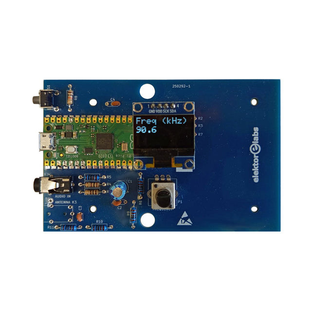
Le kit émetteur AM Elektor permet de diffuser de l’audio vers des récepteurs radio AM vintage. Basé sur un module microcontrôleur Raspberry Pi Pico, l’émetteur AM peut transmettre sur 32 fréquences dans la bande AM, de 500 kHz jusqu’à 1,6 MHz en 32 pas d’environ 35 kHz.
La fréquence est sélectionnée à l’aide d’un potentiomètre et affichée sur un écran OLED de 0,96". Un bouton-poussoir permet de basculer le mode d’émission entre Marche et Arrêt. La portée de l’émetteur dépend de l’antenne. L’antenne intégrée offre une portée de quelques centimètres, nécessitant de placer l’émetteur AM à proximité ou à l’intérieur de la radio. Une antenne boucle externe (non incluse) peut être connectée pour augmenter la portée.
Le kit émetteur AM Elektor est livré en kit de pièces que vous devez souder vous-même sur la carte.
Caractéristiques
La carte est compatible avec un boîtier Hammond 1593N (non inclus).Une alimentation 5 VDC avec connecteur micro-USB (par exemple, un ancien chargeur de téléphone) est nécessaire pour alimenter le kit (non incluse). Consommation de courant : 100 mA.
Le logiciel Arduino (nécessitant le package RP2040 Boards d’Earle Philhower) pour le kit émetteur AM Elektor ainsi que plus d’informations sont disponibles sur la page Elektor Labs de ce projet.
Liste des composants
Résistances
R1, R4 = 100 Ω
R2, R3, R8 = 10 kΩ
R5, R6, R9, R10, R11 = 1 kΩ
R7 = optionnelle (non incluse)
P1 = potentiomètre 100 kΩ, linéaire
Condensateurs
C1 = 22 µF 16V
C2, C4 = 10 nF
C3 = 150 pF
Divers
K1 = barrette 4×1 broches
K2, K3 = prise 3,5 mm
Raspberry Pi Pico
Bouton-poussoir, montage en angle
Afficheur OLED I²C monochrome 0,96"
PCB 150292-1
Projects Using Arduino IDE and the LVGL Graphics Library
The ESP32 is probably one of the most popular microcontrollers used by many people, including students, hobbyists, and professional engineers. Its low cost, coupled with rich features makes it a popular device to use in many projects. Recently, a board called the ESP32 Cheap Yellow Display (CYD for short) is available from its manufacturers. The board includes a standard ESP32 microcontroller together with a 320x240 pixel TFT display. Additionally, the board provides several connectors for interfaces such as GPIO, serial port (TX/RX), power and Ground. The inclusion of a TFT display is a real advantage as it enables users to design complex graphics-based projects without resorting to an external LCD or graphics displays.
The book describes the basic hardware of the ESP32 CYD board and provides details of its on-board connectors. Many basic, simple, and intermediate-level projects are given in the book based on the ESP32 CYD, using the highly popular Arduino IDE 2.0 integrated development environment. The use of both the basic graphics functions and the use of the popular LVGL graphics library are discussed in the book and projects are given that use both types of approaches.
All the projects given in the book have been tested and are working. The block diagram, circuit diagram, and the complete program listings and program descriptions of all the projects are given with explanations. Readers can use the LVGL graphics library to design highly popular eye-catching full-color graphics projects using widgets such as buttons, labels, calendars, keypads, keyboards, message boxes, spinboxes, sliders, charts, tables, menus, bars, switches, drop-down lists, animations, and many more widgets.
Livre : Logic Analyzers in Practice
Step-by-step instructions guide you through the analysis of modern protocols such as I²C, SPI, UART, RS-232, NeoPixel, WS28xx, HD44780 and 1-Wire. With the help of numerous experimental circuits based on the Raspberry Pi Pico, Arduino Uno and the Bus Pirate, you will learn the practical application of popular USB logic analyzers.
All the experimental circuits presented in this book have been fully tested and are fully functional. The necessary program listings are included – no special programming or electronics knowledge is required for these circuits. The programming languages used are MicroPython and C along with the development environments Thonny and Arduino IDE.
This book uses several models of flexible and widely available USB logic analyzers and shows the strengths and weaknesses of each price range.
You will learn about the criteria that matter for your work and be able to find the right device for you.
Whether Arduino, Raspberry Pi or Raspberry Pi Pico, the example circuits shown allow you to get started quickly with protocol analysis and can also serve as a basis for your own experiments.
After reading this book, you will be familiar with all the important terms and contexts, conduct your own experiments, analyze protocols independently, culminating in a comprehensive knowledge set of digital signals and protocols.
Analyseur logique USB (8 voies, 24 MHz)
Cet analyseur logique USB est un analyseur logique à 8 voies avec chaque entrée à double usage pour l'enregistrement de données analogiques. Idéal pour le débogage et l'analyse de signaux tels que I²C, UART, SPI, CAN et 1-Wire. Il fonctionne en échantillonnant une entrée numérique connectée à un dispositif en test (DUT) à une fréquence d'échantillonnage élevée. La connexion au PC se fait via USB.
Spécifications
Voies
8 voies numériques
Fréquence d'échantillonnage maximale
24 MHz
Tension d'entrée maximale
0 V ~ 5 V
Température de fonctionnement
0°C ~ 70°C
Impédance d'entrée
1 MΩ || 10 pF
Protocoles pris en charge
I²C, SPI, UART, CAN, 1-Wire, etc.
Connexion au PC
USB
Dimensions
55 x 28 x 14 mm
Télechargements
Software
Cette offre groupée contient :
Livre 'Logic Analyzers in Practice' (prix normal : 35 €)
Analyseur logique USB (8 voies, 24 MHz) (prix normal : 20 €)
Câble USB
Nappe de fils de liaison
In ESP32 programmeren voor beginners bekijken we de ESP32 en zijn voorganger, de ESP8266. Deze kleine, maar zeer krachtige Chinese chips bestaan uit een processor, geheugen, input- en outputaansluitingen en hebben draadloze netwerktoegang via WiFi.
Met dit boek tonen we hoe de programmeeromgeving Arduino werkt en hoe die kan gebruikt worden met ESP-hardware. Aan de hand van voorbeelden en projecten verduidelijken we hoe de ESP-hardware kan worden toegepast.
In vogelvlucht:
We beschrijven de opbouw van ESP-experimenten.
We tonen hoe displays worden aangesloten.
Eeprom_24c16 demonstreert hoe een externe geheugenchip wordt gebruikt om getallen en tekst op te slaan en weer uit te lezen.
Project Klok is de eenvoudige implementatie van een digitale klok.
We geven een handleiding voor het gebruik van temperatuur- en luchtvochtigheidsensoren.
Webclient laat zien hoe de ESP32 gegevens van het internet kan halen.
Met Webserver kunnen we op afstand met een pc of smartphone gegevens halen uit een ESP32, sensoren uitlezen en toestellen aan- en uitschakelen.
Een NTP-klok haalt tijdinformatie van Tijdserver. Die geeft zowel de tijd als het aantal seconden sinds 1 januari 1900. Het boek beschrijft hoe hieruit de tijd kan worden berekend.
In het laatste hoofdstuk gebruiken we het internet om nauwkeurige weerinformatie en voorspellingen op te vragen.
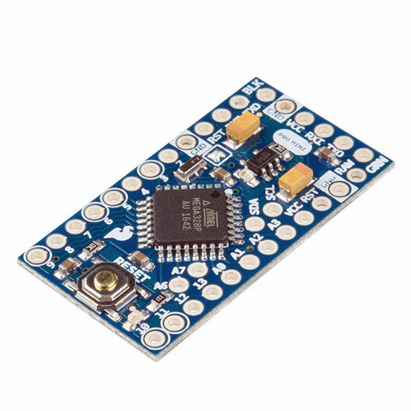
L'Arduino Pro Mini est une carte à microcontrôleur basée sur l' ATmega328P.
Elle dispose de 14 broches d'entrée/sortie numériques (dont 6 peuvent être utilisées comme sorties PWM), de 6 entrées analogiques, d'un résonateur embarqué, d'un bouton de réinitialisation et de trous pour monter des connecteurs. Un connecteur à six broches peut être connectée à un câble FTDI ou à une carte breakout de Sparkfun pour fournir une alimentation et une communication USB à la carte.
L'Arduino Pro Mini est destiné à des montages semi-permanents sur des dispositifs ou dans des expositions. La carte est livrée sans connecteurs, ce qui permet d'utiliser différents types de connecteurs ou de souder directement les fils. La disposition des broches est compatible avec celle de l'Arduino Mini.
Spécifications
Microcontrôleur
ATmega328P
Alimentation de la carte
5-12 V
Tension de fonctionnement du circuit
5 V
Broches E/S numériques
14
Broches PWM
6
UART
1
SPI
1
I²C
1
Broches d'entrée analogiques
6
Interruptions externes
2
Courant continu par broche d'E/S
40 mA
Mémoire flash
32 Ko dont 2 Ko utilisés par le bootloader
SRAM
2 Ko
EEPROM
1 KB
Fréquence d'horloge
16 MHz
Dimensions
18 x 33,3 mm
Téléchargements
Fichiers Eagle
Schémas
Plateforme tout-en-un d'apprentissage et de développement en IA pour l'Edge Intelligence
Ce kit de démarrage IA basé sur NVIDIA Jetson est une plateforme polyvalente pour l'apprentissage, le développement et l'expérimentation pratique de l'IA en périphérie (Edge AI).
Conçu pour être utilisé avec le NVIDIA Jetson Orin Nano, le kit associe un écran IPS de 11,6 pouces, une caméra motorisée (pan-tilt) de 8 mégapixels et un système d'interaction vocale basé sur l'IA.
Il comprend 30 modules fonctionnels et 38 cours Python soigneusement élaborés, allant du niveau débutant au niveau avancé. Le contenu pédagogique couvre les fondamentaux de Python, la technologie des capteurs, la vision par IA et la reconnaissance d'images.
Grâce à des exercices pratiques étape par étape — allant de la programmation de base aux applications concrètes de vision par ordinateur — ce kit constitue une plateforme idéale pour les étudiants, les makers, les développeurs et toute personne souhaitant explorer l'intelligence artificielle et l'Edge Computing.
Remarque : Le NVIDIA Jetson Orin Nano n'est pas inclus.
Caractéristiques
Conçu pour le NVIDIA Jetson Orin Nano
Module d'interaction vocale par IA
Caméra 8 MP avec contrôle panoramique et inclinaison
Prend en charge le suivi d'objets et de visages
Aucune soudure ni câblage complexe requis
Écran IPS intégré de 11,6 pouces
30 modules fonctionnels
38 leçons Python étape par étape
Interfaces d'extension I²C, UART et GPIO
Mallette de transport incluse
Spécifications
Processeur principal
Jetson Orin Nano
Nombre de capteurs
30
Conception de la carte de capteurs
Carte de capteurs intégrée ; aucune soudure ni câblage complexe requis
Écran
Écran IPS de 11,6 pouces
Résolution de l'écran
1366 x 768
Caméra
IMX219 8 MP
Interfaces d'extension
2x I²C, 1x UART, 1x IO D13, 1x IO D12
Environnement de programmation
Basé sur Python
Nombre de tutoriels
38 tutoriels créatifs
Public cible
Étudiants, enseignants, passionnés de matériel informatique
Scénarios d'application
Idéal pour apprendre la programmation d'IA et les bases de la Jetson Orin Nano
Dimensions
300 x 200 x 100 mm
Liste des modules
Module
Quantité
Capteur de température et d'humidité
1 pièce
Bouton-poussoir
4 pièces
Capteur de distance à ultrasons
1 pièce
Capteur de luminosité
1 pièce
Potentiomètre linéaire
1 pièce
Buzzer
1 pièce
Écran LCD
1 pièce
Télécommande infrarouge
1 pièce
Relais
1 pièce
Module NFC
1 pièce
Capteur de mouvement PIR
1 pièce
Joystick
1 pièce
Afficheur 4 chiffres
1 pièce
LED
1 pièce
Microphone
1 pièce
Haut-parleur
1 paire
Moteur vibrant
1 pièce
Capteur tactile
1 pièce
Matrice RVB 8x8
1 pièce
Capteur de pression atmosphérique
1 pièce
Capteur d'inclinaison
1 pièce
Moteur pas à pas
1 pièce
Accéléromètre et gyroscope
1 pièce
Capteur de gaz (MQ2)
1 pièce
Capteur à effet Hall
1 pièce
Encodeur rotatif
1 pièce
Commutateur photoélectrique en U
1 pièce
Thermistance NTC
1 pièce
Servomoteur
2 pièces
Caméra monoculaire
1 pièce
Inclus
1x Elecrow Kit de démarrage AI pour Jetson Orin Nano
1x Télécommande infrarouge
1x Carte NFC
1x Carte SD 128 Go
1x Câble GPIO 40 broches
2x Câble FPC 22 broches
2x Câble FPC 24 broches
1x Carte adaptateur Jetson DP et USB
Non inclus
NVIDIA Jetson Orin Nano
Téléchargements
Manual
Wiki
OpenClaw Install and Config Guide
Open-Source-Code mit Arduino IDE und PlatformIO
Autonomes Fahren: GPS, Accelerometer, Gyroskop
PS3-Controller
Mikrocontroller wie der Arduino und Einplatinenrechner wie der Raspberry Pi haben sich zu beliebten Komponenten entwickelt. Dritter im Bunde ist der ESP32 der Firma Espressif. Mikrocontroller dieser Baureihe zeichnen sich durch eine Vielzahl implementierter Funktionen aus, die bei einem Arduino konventioneller Prägung mit einem Atmel-AVR-Mikrocontroller erst mit weiterer Hardware möglich sind. Prominentes Beispiel sind hier die WiFi- und Bluetooth-Funktionalitäten. Gegenüber einem Raspberry Pi zeichnen sie sich durch einen deutlich geringeren Preis aus.
Allgemeine Informationen für die Realisierung eines Roboterauto-Projekts mit dem ESP32 sind leicht zu finden. Dabei handelt es sich aber oft nur um Ausführungen zu einem Teilaspekt, ohne inhaltliche oder funktionale Abstimmung. So ist nicht nur die Beschaffung der benötigten Informationen mühselig und zeitaufwändig, sie kann auch außerordentlich fehlerträchtig sein.
Ansatzpunkt dieses Buches ist, diese Lücke zu schließen. Es geht auf verschiedene Möglichkeiten eines Chassis ein, vermittelt nötige Kenntnisse und führt schrittweise von einer einfachen Motorsteuerung zu einem komplexen sensor- und sprachgesteuerten Roboterauto. Hacks rund um GPS und eine PlayStation 3 runden die Sache ab.
Inhalt
Bei der Reihenfolge der Kapitel wurde versucht – beginnend bei der Darstellung von grundlegenden Informationen – über die Lösung einfacher Aufgaben zu etwas anspruchsvolleren Techniken zu führen.
Der Mikrocontroller ESP32
Die Software erstellen
Die Stromversorgung
Rund um die Hardware
Das Chassis
Der Gleichstrommotor
Kabellose Steuerung über WiFi
Mit Sensoren Hindernisse erkennen
Eine eigene Roboterauto-App
Servo und Lichtsensor
GPS
Accelerometer / Gyroskop
PS3-Controller
Roboterauto-App
Hinweis zur Software
Die Dateien haben das Suffix (.cpp). Grund ist die Entwicklung mit PlatformIO. Mit Copy & Paste sollten sie auch in der Arduino-IDE verwendet werden können.