Produits
-
Elektor Labs Elektor Audio DSP FX Processor (Nouvelle Révision)
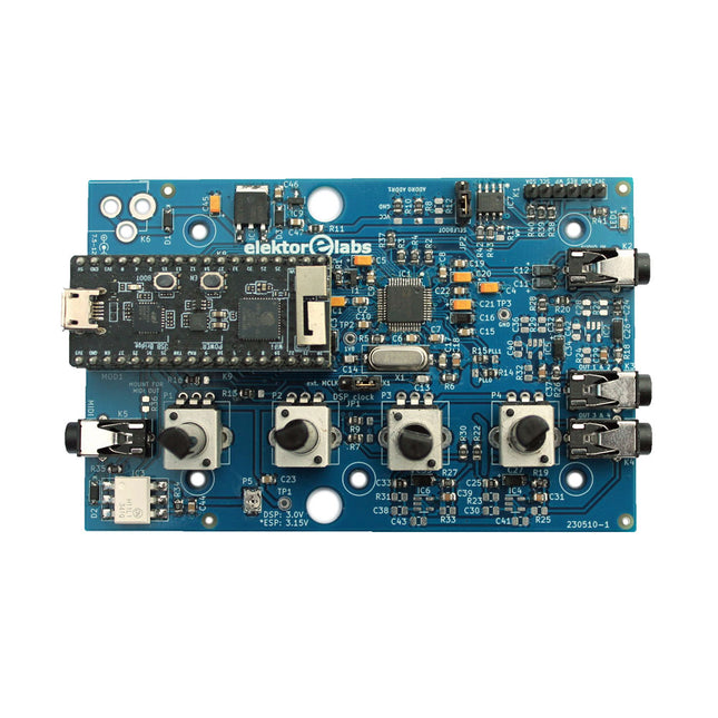
Le Elektor Audio DSP FX Processor combine un microcontrôleur ESP32 et un DSP Audio ADAU1701 d'Analog Devices. Outre un noyau DSP programmable par l'utilisateur, l'ADAU1701 intègre des convertisseurs analogique-numérique et numérique-analogique de haute qualité et dispose d'un port I²S. Cela le rend approprié comme interface audio de haute qualité pour l'ESP32. Les programmes pour l'ESP32 peuvent être créés avec Arduino, Platform IO, CMake ou en utilisant Espressif IDF d'une autre manière. Les programmes pour les DSP audio ADAU7101 sont créés avec l'outil de programmation visuelle gratuit SigmaStudio en glissant et déposant des blocs d'algorithmes prédéfinis sur un canevas. Applications Sink audio Bluetooth/Wi-Fi (par ex. haut-parleur) et source Pédale d'effet guitare (stomp box) Synthétiseur musical Générateur de sons/fonctions Filtre cross-over programmable pour haut-parleurs Processeur d'effets audio avancé (réverbération, chorus, pitch shifting, etc.) Appareil audio connecté à Internet Plate-forme d'expérimentation DSP MIDI sans fil Convertisseur MIDI vers CV et bien d'autres... Spécifications Processeur audio numérique ADAU1701 28/56 bits, 50 MIPS prenant en charge des taux d'échantillonnage allant jusqu'à 192 kHz Microcontrôleur double cœur ESP32 32 bits avec Wi-Fi 802.11b/g/n et Bluetooth 4.2 BR/EDR et BLE 2 entrées audio 24 bits (2 V RMS, 20 kΩ) 4 sorties audio 24 bits (0,9 V RMS, 600 Ω) 4x potentiomètres de contrôle Entrée et sortie MIDI Port d'extension I²C Fonctionnement multimode Alimentation : USB 5 V CC ou 7,5-12 V CC (prise cylindrique, broche centrale GND) Consommation de courant (moyenne) : 200 mA Inclus 1x Carte Audio DSP FX Processor (assemblée) 1x ESP32-PICO-KIT 2x Cavaliers 2x Connecteurs à 18 broches (female) 4x Potentiomètres de 10 Ko Téléchargements Documentation GitHub
€ 99,95€ 84,95
Meilleur prix
-
Elektor Digital Elektor Circuit Spécial 2023 (PDF)
Le téléchargement intégral de ce numéro est disponible pour nos membres GOLD et GREEN sur le site Elektor Magazine !Pas encore membre ? Cliquez ici.petite alimentation solairelumière du soleil en entrée, 3,3 V en sortiecommutateur audio stéréo statiquesans clics ni pièces mobilesgrand chiffre RGBavec LED traversants de type WS2812préamplificateur de microphone avec alimentation fantôme 48 Vidéal pour le podcasting et la sonorisation progénérateurs d'ondes carrées avec commande de rapport cyclique et de fréquencemontages simples avec des CI CMOS et TTLcompresseur Dynamique Simpleavec contrôle doux et un son chaleureuxserrure électronique simpleredresseur actifde 2 à 40 V jusqu'à 3 A avec suppression du courant inversecommutation marche/arrêt pour enceintes activesconvertisseur symétrique/asymétriqueavec filtre RFI et protection CC2023 : l'odyssée de l'IAorigine et évolutionrégulateur de vitesse pour ventilateur ou aérateuravec modes manuel et thermostatPlateforme Projets Arduino : dernières nouvellesnouveaux projets de la communautémoniteur de surchargesurveillez les lignes électriques pour détecter les courants excessifsclignotement nocturne sans transistorsun oscillateur ne comportant que des composants à deux filsgénérateur de code morseutilisez-le comme balise ou dispositif d'apprentissage !CNA vidéo programmabletraite tous les formats jusqu'à RGB888un tout petit pianosans pièces mobilesdouble-dé électronique sans microcontrôleurdeux dés sur un seul circuit imprimé – plus quelques astuces de conceptioneffaroucheur électroniquecircuits qui amusent, inspirent et étonnentthermomètre LC-LP-HAmesures précises et affichage binairegénérateur de distorsion harmoniquegénérer volontairement de la distorsionindicateur de surchauffe à thyristorutilisation non conventionnelle des composants électroniquesune bascule CTPun drôle d'oiseauun classique d'Elektor qui émet des gazouillislampe au néon avec microcontrôleursource de courant stable en températureéliminer la dérive de température des CI sources de courantcorrecteur d'aigus d'ordre 2 réglablecorrection auditive pour personnes âgéesEdwin revientaprès 53 ans d'absencemachine à sous à levierun classique d'Elektor simple, amusant, nostalgique et éducatifrésistance variable simple à contrôle numériqueprotection contre les fuites d'eauprotection et alarme contre les fuites d'eauminuterie économique avec arrêt automatiquenécessite 0,0 mW en mode éteint !ChatGPT fait de l'ArduinoZD-mètremesure de la tension de coude des diodes Z ≤ 100 Vtesteur de servosContrôleur Windows ESP32 avec logiciel gratuitcircuits analogiques et mixtes de Microchipgestion de l'alimentation économe en énergie et traitement de signalstandards d'interfacesfiltrage et protection contre leurtensions pour le bus I²Cmoniteur de batterie Li-Ionl'indicateur de charge résiduelle fournit un retour d'information visuelsouris PS/2 comme codeur rotatif (et plus…)interrupteur crépusculaire simplepour moderniser vos luminaires ou vos installationscommande de pompe à eauprotégez-vous contre la montée des eauxboule de Noël solaire avec radio FMtout ce que vous voulez pour Noël, c'est celacapteur de vibrations avec relaistapotez ou secouez pour allumertesteur de continuitésensible et discretbouton-poussoir marche/arrêtContrôleur pour mini-perceuse 2023révision d'un projet de 1980détecteur de vibration numériquetransformez les vibrations en impulsions précisesprotection contre l'inversion de polarité avec faible chute de tensionétalon de fréquence peu coûteuxpetit simulateur DCF77une référence précise pour le Fake-Timele Lilygo T-PicoC3combine un RP2040 et un ESP32-C3 avec un écran TFT couleurHexadoku
€ 10,95
-
Elektor Digital Elektor Circuit Special 2024 (PDF)
Le téléchargement intégral de ce numéro est disponible pour nos membres GOLD et GREEN sur le site Elektor Magazine ! Pas encore membre ? Cliquez ici. charge électronique pour les tests à haute intensitéde la nécessité à l'innovation suppresseur de voixcircuit pour un karaoké instantané sélecteur audio A/B avec réglage de gaincommuter de l'entrée micro à l'entrée ligne optimiser la rechrage du LIR2032prenez soin de vos piles bouton la détection tactile en toute simplicitéun guide de fabrication pour n'importe quel microcontrôleur interrupteur universel à télécommandeune nouvelle vie pour les vieilles télécommandes une boite à meuh avec un microcontrôleurproduire des sons amusants à l'aide d'un microcontrôleur interface de batterie externe USB alimenter les appareils à faible consommation avec des batteries externesune Solution pour les maintenir actives mini-ampli audio de classe A avec sortie en courantpiloter les haut-parleurs en courant au lieu de tension module pseudo-symétriqueCMRR élevé avec des liaisons audio asymétriques chargeur automatique d'accu Ni-MHrechargez toutes vos batteries simultanément ! protection pour alimentation électrique basée sur un thyristor lecteur d'empreintes digitalesdispositif utile d'identification convertisseur de puissance DC-DC 3Aaméliorer vos sources de tension fixes innovations de la plateforme Arduino Project Hubnouveaux projets de la communauté contrôle à distance du chauffe-eaudétection de tension et de courant pour les lignes à courant alternatif atténuateurs pour signaux audio (1)sélection par cavaliers cure de jouvence pour votre vieux chargeur (1)ne le jetez pas, modernisez-le ! une carte pour « The Blue »circuit imprimé pour le potentiomètre motorisé d'Alps référence 50 Hz à partir d'une tension secteur 60 Hzconversion de 50 Hz à 60 Hz isolateurs numériquesréalisation facile de l’isolation galvanique amplificateur mono Hi-Fi compact de 12 Wpetit mais puissant générateur de rampe LM386 générateur triphaséavec Raspberry Pi Pico ouverture de porte pour les personnes ayant des talents musicaux classique d’Elektor : synthétiseur Surfgénérateur d’ambiance océanique relaxante (de Chhhh à Zzzz) cure de jouvence pour votre vieux chargeur (2)ne le jetez pas, modernisez-le ! surveillance du courant d'une lampe avec Raspberry Pi Pico télégraphie infrarouge Fnirsi SWM-10appareil portable de soudage par point intelligent pour réparer vos packs d’accumulateur Codec audio stéréo pour ESP32 et Ciela mesure audio : pas de panique techniques de soudure à l’étain faites-le correctement dès maintenant ! atténuateurs pour signaux audio (2) sélection par relais alimentation USB-CDrawing Power from USB-C Power Adapters trois circuits avec deux et trois puces 4017 comptez sur les 4017 composants actifs - la diode un minuteur pour des délais ultra-Longs réglez-le et oubliez-le ! Jack In & Jack Out maillon d’E/S pour chaînes audio alimenter un ESP32 à partir d'une seule cellule Li-ion Hexadoku
€ 10,95
-
Elektor Circuit Special 2025 (FR)
Le téléchargement intégral de ce numéro est disponible pour nos membres GOLD et GREEN sur le site Elektor Magazine ! Pas encore membre ? Cliquez ici. adaptateur de mesure USBTest du courant et des signaux des ports USB sortie boucle de courant 4-20 mA pour Arduino UnoUne interface de boucle de courant fiable et insensible aux interférences électromagnétiques commande automatique pour aspirateurGardez votre établi propre générateur DDS avec ATtiny testeur d'ampli-op V2Nouveau circuit imprimé – désormais compatible avec les CMS amplificateur audio à tube 550 mWson chaleureux des tubes à vide surveillance des fusiblesavec une LED clignotante préamplificateur RIAA HQExploitez tout le potentiel sonore de vos disques vinyles ! Outil de réglage pour platines vinylesGénérateur de lumière stroboscopique 100–120 Hz basé sur Arduino Elektor Classics : ampli vidéo gradateur à télécommande infrarougeContrôlez votre éclairage avec confort et précision comment utiliser switch…case avec des chaînes de caractères en C++/EDI Arduino détecteur d’aimantsAvec un simple capteur à effet Hall bouton de mise sous tension intelligent pour Raspberry PiUne solution pour Raspberry Pi jusqu’au modèle 4 astuces clés pour makersDes conseils pros pour vos projets projets pratiques avec le timer 555Commande de moteur CC et jeux de rapidité moniteur de charge CA simpleÉconomisez de l'énergie grâce à un appareil simple batteries externes en parallèleTrois jours d’autonomie VFO jusqu’à 15 MHzRéalisation avec un Raspberry Pi Pico accordeur de violon avec ATtiny202 Elektor Classics : ampli vidéo pour TV N&B capacimètre20 pF à 600 nF horloge quasi analogique Mk IIDeux anneaux LED pour les heures et les minutes concevez sans limites(grâce à l’écosystème complet d’Arduino) dé à lampes néon Elektor Classics : indicateur d'accord RTTY solutions matérielles inspirantes pour vos projets ESP Elektor Classics : alimentation 3 A LED RGB avec circuit de commande intégréLumière de précision : les ICLED établissent de nouvelles normes expérience : un Thérémine analogico-numérique ?Combiner des capteurs numériques modernes avec l’intemporel générateur analogique XR2206 carte émetteur-récepteur audio ESP32 (1)Démo : lecture de fichiers WAV depuis une carte SD infographies : Circuits et conception de circuits 2025 petit mixeur audioUne conception polyvalente et modulable minuteur intelligent pour éclairage d’escalierÉconomisez encore plus sur votre facture d’énergie ! modernisez vos voletsContrôlez les systèmes Velux avec un ESP32 et MQTT chauffe-pieds à transistorsConfort économe en énergie le quadricoptère M5Stamp Fly est-il le prochain drone Tello ? (Revue) optimiser la portée Wi-Fi de l’ESP32-C3 SuperMiniUne modification d’antenne simple et efficace station de soudage à air chaud ZD-8968Un outil de travail économique ou uniquement de l'air chaud ? testeur de radar de reculDétecter les pannes du système d’aide au stationnement d’un véhicule
€ 15,50
-
Elektor Digital Elektor Circuit Special 2025 (PDF) FR
Le téléchargement intégral de ce numéro est disponible pour nos membres GOLD et GREEN sur le site Elektor Magazine ! Pas encore membre ? Cliquez ici. adaptateur de mesure USBTest du courant et des signaux des ports USB sortie boucle de courant 4-20 mA pour Arduino UnoUne interface de boucle de courant fiable et insensible aux interférences électromagnétiques commande automatique pour aspirateurGardez votre établi propre générateur DDS avec ATtiny testeur d'ampli-op V2Nouveau circuit imprimé – désormais compatible avec les CMS amplificateur audio à tube 550 mWson chaleureux des tubes à vide surveillance des fusiblesavec une LED clignotante préamplificateur RIAA HQExploitez tout le potentiel sonore de vos disques vinyles ! Outil de réglage pour platines vinylesGénérateur de lumière stroboscopique 100–120 Hz basé sur Arduino Elektor Classics : ampli vidéo gradateur à télécommande infrarougeContrôlez votre éclairage avec confort et précision comment utiliser switch…case avec des chaînes de caractères en C++/EDI Arduino détecteur d’aimantsAvec un simple capteur à effet Hall bouton de mise sous tension intelligent pour Raspberry PiUne solution pour Raspberry Pi jusqu’au modèle 4 astuces clés pour makersDes conseils pros pour vos projets projets pratiques avec le timer 555Commande de moteur CC et jeux de rapidité moniteur de charge CA simpleÉconomisez de l'énergie grâce à un appareil simple batteries externes en parallèleTrois jours d’autonomie VFO jusqu’à 15 MHzRéalisation avec un Raspberry Pi Pico accordeur de violon avec ATtiny202 Elektor Classics : ampli vidéo pour TV N&B capacimètre20 pF à 600 nF horloge quasi analogique Mk IIDeux anneaux LED pour les heures et les minutes concevez sans limites(grâce à l’écosystème complet d’Arduino) dé à lampes néon Elektor Classics : indicateur d'accord RTTY solutions matérielles inspirantes pour vos projets ESP Elektor Classics : alimentation 3 A LED RGB avec circuit de commande intégréLumière de précision : les ICLED établissent de nouvelles normes expérience : un Thérémine analogico-numérique ?Combiner des capteurs numériques modernes avec l’intemporel générateur analogique XR2206 carte émetteur-récepteur audio ESP32 (1)Démo : lecture de fichiers WAV depuis une carte SD infographies : Circuits et conception de circuits 2025 petit mixeur audioUne conception polyvalente et modulable minuteur intelligent pour éclairage d’escalierÉconomisez encore plus sur votre facture d’énergie ! modernisez vos voletsContrôlez les systèmes Velux avec un ESP32 et MQTT chauffe-pieds à transistorsConfort économe en énergie le quadricoptère M5Stamp Fly est-il le prochain drone Tello ? (Revue) optimiser la portée Wi-Fi de l’ESP32-C3 SuperMiniUne modification d’antenne simple et efficace station de soudage à air chaud ZD-8968Un outil de travail économique ou uniquement de l'air chaud ? testeur de radar de reculDétecter les pannes du système d’aide au stationnement d’un véhicule
€ 10,95
-
Elektor Digital Elektor circuits de vacances 2022 (PDF)
Plus de 50 circuits et projetsSirène de style américainDeux codeurs rotatifs sur une seule entrée analogiqueConstruire un gradateur numérique 220-V CA avec ArduinoSource de courant pour LEDDétecter quatre contacts avec une seule brochePetit interrupteur marche/arrêt avec protection de batterieDistributeur de désinfectant DIY pour les mainsUn orgue électronique simpleAmpli stéréo ultrasimpleInterrupteur activé par le son pour amplificateursBalanced/Unbalanced ConverterFiltre externe pour réseau électriqueTélécommande comodoBoîte de direct pour smartphoneAmusez-vous avec les feux de circulationCommande de thyristor avec un seul boutonPosemètre quasi analogique pour chambre noireCircuits à volonté de la communauté Hackster.ioMinuteur analogique de bronzageEncore une interface LCD à un seul filGénérateur PWM simple avec AVR ATtiny13Une seconde vie pour les pilesInterrupteur tactile pour les lampes à LEDTesteur de LED et d'interrupteurs DIPTesteur de contrôle IR Go/No-GoTesteur de semiconducteurs de puissanceSPI pour les LED WS2812(B)Mesure des inductances de puissanceUne seule prise pour le RPi et le CN/A audioAccessoire de test DIY pour le compteur LCRAmpèremètre ArduinoOrgue à deux doigtsCalibrateur de CAN à faible bruitConvertisseur élévateur DC/DCDeux potentiomètres sur une entrée numériqueCapteur de proximité acoustiqueCapteur de radiateur sans pileDétecter les micros et les caméras sans filMinuteur pour éclairage intérieur de voitureSimulateur de bougieMinuteur numérique de cuisineMilliohmmètreMinuteur de production d'eau chaudeChargeur simple pour les batteries 2S 18650Référence de fréquence avec ATtinyCommutateur IR à faible puissanceRecycler le chargeur de téléphone de votre voiturePréamplificateur de microphone pour ArduinoFiltres IEM DIYDé électronique sans microcontrôleurCondensateur digitalClignotant à LED autochargeableAussi dans ce numéroKiCad 6 – Cinq fonctionnalités à prendre en compteFlashback – Ordinateur SC/MP d'ElektorInterview – Faire de l'art avec l'électricitéMon premier circuit imprimé – Se lancer avec KiCadMinimiser le matériel avec un logiciel intelligentInfographie – Faits et chiffresNouveaux dispositifs d'AnalogFlashback – Le détecteur de métaux d'ElektorHexadoku – Casse-tête pour elektorniciens
€ 10,95
-

Elektor Edge Impulse Guest Edition 2025 (FR)
Le téléchargement intégral de ce numéro est disponible pour nos membres GOLD et GREEN sur le site Elektor Magazine ! Pas encore membre ? Cliquez ici. qu’est-ce que l’edge AI ?L’IA, intégrée à l’appareil découvrez Edge Impulse StudioConcevez et déployez facilement des modèles d’IA en périphérie détection de mots-clés avec Edge ImpulseCollecter, entraîner et déployer contrôle d’appareils par commande vocale avec le Nordic Thingy:53 Termes clés pour comprendre l’edge AI et le machine learning cours accéléré : démarrez avec Edge ImpulseApprenez à collecter, entraîner et déployer un modèle ML avec l’Arduino Nano 33 BLE Sense un nouveau chapitre pour ArduinoD’une carte pour amateurs à une plateforme d’edge computing premiers pas avec la détection d’objets sur des appareils edge détection de défauts sur circuits imprimésVision par ordinateur avec Raspberry Pi adapter l’IA aux appareils les plus compacts optimiser l’efficacité énergétique des appareils edge AI alimentés sur batterie grille-pain intelligentL’IA qui reconnaît le toast parfait Thundercomm Rubik Pi 3Raspberry Pi et l’edge AI, enfin réunis Leadership, ML embarqué et révolution de l’IA en périphérie modèles vision-langage en périphérieCascade de modèles pour une meilleure fiabilité découvrez Edge ImpulseQuestions de la communauté Elektor mise à jour du projet n°5 : Compteur d’énergie ESP32Utiliser l’Edge AI pour identifier les charges domestiques reconnaissance de mouvements avec détection d’anomaliesUn tutoriel détaillé système de ventilation intelligent : fusion des données sonores et environnementalesUtilisation d’un microcontrôleur double-cœur et du ML pour l’automatisation des fenêtres et persiennes intégrer la commande vocale aux écouteurs et aux casques l'IA en périphérie : au cœur des appareils de demain
€ 16,50
-

Elektor Digital Elektor Edge Impulse Guest Edition 2025 (PDF) FR
Le téléchargement intégral de ce numéro est disponible pour nos membres GOLD et GREEN sur le site Elektor Magazine ! Pas encore membre ? Cliquez ici. qu’est-ce que l’edge AI ?L’IA, intégrée à l’appareil découvrez Edge Impulse StudioConcevez et déployez facilement des modèles d’IA en périphérie détection de mots-clés avec Edge ImpulseCollecter, entraîner et déployer contrôle d’appareils par commande vocale avec le Nordic Thingy:53 Termes clés pour comprendre l’edge AI et le machine learning cours accéléré : démarrez avec Edge ImpulseApprenez à collecter, entraîner et déployer un modèle ML avec l’Arduino Nano 33 BLE Sense un nouveau chapitre pour ArduinoD’une carte pour amateurs à une plateforme d’edge computing premiers pas avec la détection d’objets sur des appareils edge détection de défauts sur circuits imprimésVision par ordinateur avec Raspberry Pi adapter l’IA aux appareils les plus compacts optimiser l’efficacité énergétique des appareils edge AI alimentés sur batterie grille-pain intelligentL’IA qui reconnaît le toast parfait Thundercomm Rubik Pi 3Raspberry Pi et l’edge AI, enfin réunis Leadership, ML embarqué et révolution de l’IA en périphérie modèles vision-langage en périphérieCascade de modèles pour une meilleure fiabilité découvrez Edge ImpulseQuestions de la communauté Elektor mise à jour du projet n°5 : Compteur d’énergie ESP32Utiliser l’Edge AI pour identifier les charges domestiques reconnaissance de mouvements avec détection d’anomaliesUn tutoriel détaillé système de ventilation intelligent : fusion des données sonores et environnementalesUtilisation d’un microcontrôleur double-cœur et du ML pour l’automatisation des fenêtres et persiennes intégrer la commande vocale aux écouteurs et aux casques l'IA en périphérie : au cœur des appareils de demain
€ 10,95
-
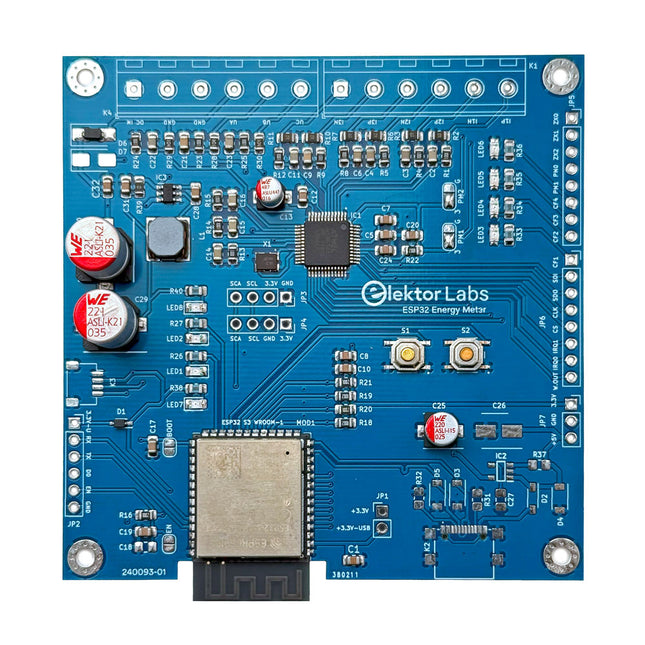
Elektor Labs Compteur d'énergie ESP32 Elektor
Le compteur d'énergie Elektor ESP32 est un appareil conçu pour la surveillance de l'énergie en temps réel et l'intégration de la maison connectée. Alimenté par le microcontrôleur ESP32-S3, il offre des performances robustes avec des fonctionnalités modulaires et évolutives. L'appareil utilise un transformateur abaisseur de 110/230 VAC à 12 VAC pour l'échantillonnage de tension, garantissant ainsi l'isolation galvanique et la sécurité. Sa configuration PCB compacte comprend des borniers à vis pour des connexions sécurisées, un connecteur Qwiic pour des capteurs supplémentaires et un connecteur de programmation pour une configuration directe ESP32-S3. Le compteur d'énergie est compatible avec les systèmes monophasés et triphasés, ce qui le rend adaptable à diverses applications. Le compteur d'énergie est simple à configurer et s'intègre à Home Assistant, offrant des capacités de surveillance en temps réel, d'analyse historique et d'automatisation. Il fournit des mesures précises de tension, de courant et de puissance, ce qui en fait un outil précieux pour la gestion de l'énergie dans les maisons et les entreprises. Caractéristiques Surveillance complète de l'énergie : Obtenez des informations détaillées sur votre consommation d'énergie pour une gestion plus intelligente. Logiciel personnalisable : Adaptez les fonctionnalités à vos besoins en programmant et en intégrant des capteurs personnalisés. Prêt pour la maison connectée : Compatible avec ESPHome, Home Assistant et MQTT pour une intégration complète à la maison connectée. Conception sûre et flexible : Fonctionne avec un transformateur abaisseur de 110/230 VAC à 12 VAC et comporte une carte CMS pré-assemblée. Démarrage rapide : Comprend un capteur de transformateur de courant et un accès à des ressources de configuration gratuites. Spécifications Microcontrôleur ESP32-S3-WROOM-1-N8R2 CI de mesure d'énergie ATM90E32AS Indicateurs d'état 4 LED pour l'indication de la consommation électrique2 LED programmables pour les notifications d'état personnalisées Entrée utilisateur 2x boutons-poussoirs pour le contrôle utilisateur Afficher la sortie Écran OLED I²C pour une visualisation de la consommation électrique en temps réel Tension d'entrée 12~16 VAC (via un transformateur abaisseur 110/230 VAC à 12 VAC) Capteur de courant à pince YHDC SCT013-000 (100 A/50 mA) inclus Intégration de la maison connectée ESPHome, Home Assistant et MQTT pour une connectivité transparente Connectivité En-tête pour la programmation, Qwiic pour l'extension du capteur Applications Prend en charge les systèmes de surveillance de l'énergie monophasés et triphasés Dimensions 79,5 x 79,5 mm Inclus 1x Carte partiellement assemblée (les composants CMS sont pré-montés) 2x Connecteurs de bornier à vis (non montés) 1x Transformateur de courant YHDC SCT013-000 Requis Transformateur de puissance non inclus Téléchargements Datasheet (ESP32-S3-WROOM-1) Datasheet (ATM90E32AS) Datasheet (SCT013-000) Frequently Asked Questions (FAQ) Du prototype au produit fini Ce qui a commencé comme un projet innovant visant à créer un compteur d'énergie fiable et convivial utilisant le microcontrôleur ESP32-S3 est devenu un produit robuste. Initialement développé en tant que projet open source, le compteur d'énergie ESP32 visait à fournir une surveillance précise de l'énergie, une intégration de maison intelligente et bien plus encore. Grâce à un développement méticuleux du matériel et du micrologiciel, le compteur d'énergie se présente désormais comme une solution compacte et polyvalente pour la gestion de l'énergie.
€ 79,95€ 64,95
Meilleur prix
-
Elektor Digital Elektor invitation éditoriale Espressif 2023 (PDF)
Le téléchargement intégral de ce numéro est disponible pour nos membres GOLD et GREEN sur le site Elektor Magazine ! Pas encore membre ? Cliquez ici. accélérer l'innovation IdO cadre photo couleur à encre électronique Wi-Fi tutoriel ESP-Launchpadflashage des micrologiciels en quelques minutes ESP32 et ChatGPTvers un système d'autoprogrammation... Talkie-walkie avec ESP-NOWPas tout à fait Wi-Fi, pas tout à fait Bluetooth non plus... de l'idée au circuit avec l'ESP32-S3construire un prototype avec les puces Espressif innovation des puces AIoTentretien avec Teo Swee-Ann, PDG d'Espressif simuler l'ESP32 avec Wokwile jumeau numérique de votre projet essai de l'ESP32-S3-BOX-3une plateforme de développement AIoT complète bien s?équiper pour mieux travaillerconseils et astuces des ingénieurs d?Espressif l'histoire de l'ESP RainMakerComment nous avons construit « votre » nuage IdO assemblage du kit du Cloc 2.0 d?Elektorun produit Elektor déballé par Espressif le lancement de l'ESP32-P4la nouvelle ère des microcontrôleurs Rust et les systèmes embarquésdeux outils puissants pour le développement qui sont les développeurs de solutions embarquées Rust ?comment Espressif développe le langage Rust embarqué pour l'ESP32 Série de SoC Espressif une API avec les Solutions d'Espressifavec les capacités et les fonctionnalités du protocole ISOBUS la carte VGA ESP32-S3le voyage passionnant de Bitluni dans la conception de produits empreinte acoustique sur ESP32identification de chansons avec le projet open source Olaf arbre de Noël circulaire 2023célébration high-tech des fêtes de fin d'année une vie plus confortable et plus facileun projet amateur basé sur le module ESP8266 Espressif comment construire des applications IoT Sans Expertise Logicielle Avec la plateforme IoTavec la plateforme IoT Blynk et le matériel Espressif concevoir une Interface Graphique sur ESP32 développement IoT rapide et facile avec M5Stack prototypage d'un compteur d'énergie basé sur l'ESP32 un distributeur à valeur ajoutée de solutions IdO et plus encore En détail : entretien avec Arduino sur le Nano ESP32Alessandro Ranellucci et Martino Facchin abordent la collaboration avec Espressif innovation des puces IdOles idées d'Espressif simplifier le développement des microcontrôleurs avec ESP-IDF Privilege Separation un serveur de reconnaissance de la parole open-source......et l'ESP BOX l??il qui réfléchitreconnaissance faciale et plus encore, utilisant l?ESP32-S3-EYE commutateur alimenté par pile bouton, basé sur un ESP32-C2évaluation de la conception et des performances la maison intelligente évolue avec Matterlibérer le potentiel de l'IdO pour les maisons intelligentes l'essor de la maison intelligente connectée
€ 10,95
-
Elektor Digital Elektor Janvier/Février 2020 (PDF)
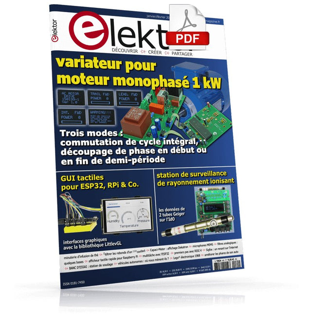
GUI tactiles – pour ESP32, RPi & Co.interfaces graphiques utilisateur avec la bibliothèque LittlevGL« pas seulement un projet comme un autre »Entretien avec Gábor Kiss-Vámosi, le développeur de LittlevGLCapaci-Meteraffichage à LED de type Dekatron sur deux chiffresCocomment fifiltrer les rerebonds d'un concontact mémécanique ?Un interrupteur est soit ouvert, soit fermé, n'est-ce pas ?filtres analogiques : quelques basesla magie des réseaux de filtrage est l'un des phénomènes les plus saisissants de l'électroniquebureau d'études - zone DDéveloppement en coursstation de surveillance de rayonnement ionisantPublie les données de 2 tubes Geiger sur les plates-formes IdOmultitâche en pratique avec l'ESP32programmation de tâches avec FreeRTOS et l'EDI Arduinomises au point & mises à jourCorrections – questions – réponsesaméliorer soi-même les phares de son auto ?Légal ou illégal, ce n'est pas égal !BANC D'ESSAI : station de soudage numérique ToolcraftArduino Pro IDE : mes premières impressionsComparaison de deux caméras de vision thermiqueexpérience vécueinstaller un labo et un atelier d'électroniqueélectronique analogiqueÉtude de cas nº 1 - Section 1 : microphone MEMS... 1-2-3 test 1-2-3minuterie d'infusion de théExercice de récupération d'énergie avec convertisseur thermoélectriquevariateur pour moteur monophasé 1 kWTrois modes de fonctionnement : commutation de cycle intégral, découpage de phase en début ou en fin de demi-périodeafficheur tactile 3,5 pouces rapide pour Raspberry PiParfait pour la vidéo, mais pas plus cherce labo-ci n'est pas ce labo-làmontre-moi ton labo, je te dirai qui tu es.Premiers pas avec RISC-VEssai de la carte LoFiveun géotraceur LoRa défie Elektor LabsPetits tracas du concepteur avec leur solution en geléeSigfox : un renard sur l'internet des objets (2)Inscription au réseau Sigfoxdémarrer en électronique... est plus facile qu'on ne l'imagine !retour des petits circuits…et des bonnes petites idées de projets Elektorvéhicules autonomes : où nous mènent-ils ?L'état de l'art (abrégé)Innovation 4.0 : dialogue d'innovateurs et d'entrepreneursCoffret Lego électronique, millésime 1968Les jouets électroniques fascinent encore 50 ans plus tardça dépasse l'électroniqueJauger un pont pour jauger la villeHexadoku – casse-tête pour elektorniciens
€ 10,95
-
Elektor Digital Elektor Janvier/Février 2021 (PDF)
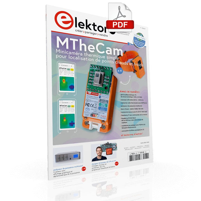
SUPERCHARGEUR LIPO EN KITChargeur, booster et protecteur LiPo proposé par GreatScott & ElektorMINI CAMÉRA THERMIQUE MTHECAMMinicaméra thermique simple pour localisation de points chauds et froidsBANC D'ESSAI : WELLER WE 1010Station de soudageGAGNANTS DU CONCOURS ELECTRONICA FAST FORWARD 2020GÉNÉ AUDIONUMÉRIQUE DE SIGNAUX DE TEST I2SSinus numérique 1 kHz, à 32 bits, échantillonné à 192 kHz, réglable de 0 à –110 dBRASPBERRY PI AUX COMMANDES DE LA MAISONRPi furète sur 433,92 MHzSIMULE TES CIRCUITS EN LIGNESUR LE VIFEntre ordre et chaosDÉBUTER EN ÉLECTRONIQUE... (5)…est moins difficile qu'on ne l'imagine !OHM SUITE OHMNi CPU ni ALU, juste un opérateur logique NOR à deux transistorsCONNECTEZ VOTRE THERMOSTAT AVEC ESPHOMEUne tentative pour faire de la domotique comme il fautBUREAU D'ÉTUDES – ZONE DD comme développement, comme débrouillardise et dur-à-cuireELLES SONT PETITES MAIS FONT DE BELLES CHOSESLes pépites d'ElektorRASPBERRY PI FULL STACKRPi et RF24 au cœur d'un réseau de capteursMULTITÂCHE EN PRATIQUE AVEC L'ESP32 (6)Groupes d'événementsANALYSEUR DE PUISSANCE MULTICANALAvec affichage graphique et alphanumérique de la puissance sur 3 canauxCONCEPTION DE FILTRES ANALOGIQUES (3)Filtres passifsBANC D'ESSAI : MODULE DE MESURE SANS FIL JOY-IT VAX-1030NOUVEAU LCR-MÈTRE 50 HZ - 2 MHZ (2)Fonctionnement, étalonnage et microprogrammeERREURS FÉCONDESConseils sur les régulateurs de tension et sur la conception des circuits imprimés, etc.CORRECTIONS, MISES À JOUR ET COURRIER DES LECTEURSJAVA SUR RASPBERRY PIEntretien avec Frank DelporteANALYSE DE DONNÉES ET INTELLIGENCE ARTIFICIELLE EN PYTHONInterpréter les données réelles avec NumPy, pandas et le scikit-learnPROPELLER 2 DE PARALLAX (1)Une découverteOBSERVATOIRE DU MATÉRIEL LIBREÉvaluation communautaire du matériel à source ouverteHEXADOKU
€ 10,95
-
Elektor Digital Elektor Janvier/Février 2022 (PDF)
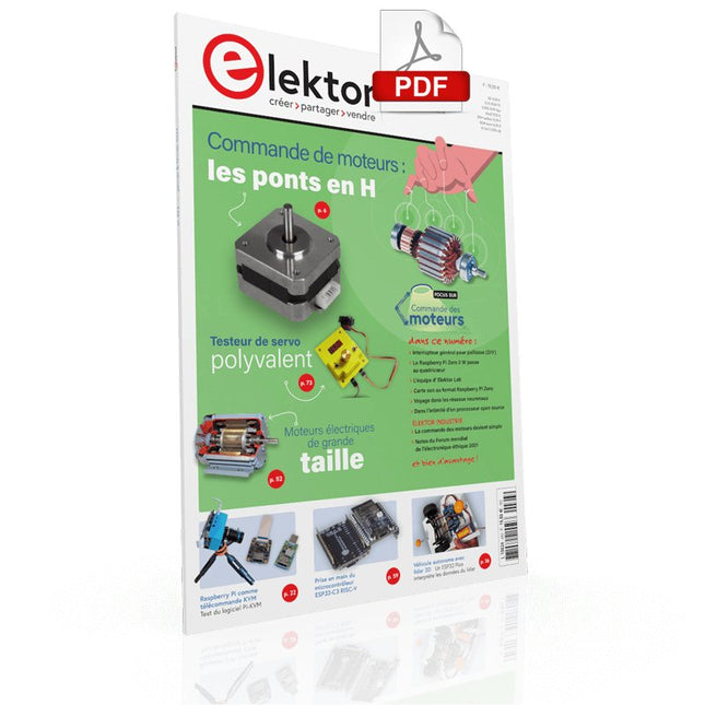
COMMANDE DE MOTEURS : LES PONTS EN HIntroduction aux moteurs CC, pas à pas et sans balaisL'ÉQUIPE D'ELEKTOR LABNotre approche, nos outils préférés et plus encoreRASPBERRY PI COMME TÉLÉCOMMANDE KVMTest du logiciel Pi-KVMIQAUDIO CODEC ZEROCarte son au format Raspberry Pi ZeroLE PROJET PIKVM ET SES ENSEIGNEMENTSEntretien avec Maxim DevaevVÉHICULE AUTONOME AVEC LIDAR 2DUn ESP32 Pico interprète les données du lidarLE RASPBERRY PI ZERO 2 W PASSE AU QUADRICOEURNOTES DU FORUM MONDIAL DE L'ÉLECTRONIQUE ÉTHIQUE 2021COMMANDE DE MONTEURLa commande des moteurs devient simpleMOTEURS ÉLECTRIQUES DE GRANDE TAILLEPrincipes de base et informations utilesPRISE EN MAIN DU MICROCONTRÔLEUR ESP32-C3 RISC-VPROTÉGEZ-VOUS ET PROTÉGEZ LES AUTRES !Interrupteur général pour paillasse (DIY)CRÉATION D'INTERFACES GRAPHIQUES EN PYTHON ÈME 2Mon nom n'est pas BondGAGNANTS DU CONCOURS FAST FORWARD 2021 DU SALON PRODUCTRONICATESTEUR DE SERVO POLYVALENTVérification du comportement en l'absence de fiche techniqueMODBUS SANS FIL (PARTIE 2)Logiciel de la carte Modbus TCP sans filVOYAGE DANS LES RÉSEAUX NEURONAUX (3E PARTIE)Les neurones pratiquesDANS L'INTIMITÉ D'UN PROCESSEUR OPEN SOURCEExtrait : résultats des FPGA Lattice et XilinxDÉMARRER EN ÉLECTRONIQUE... (10)Toujours la bobine, mais avec ses applications pratiques dans l'audio.PROJET 2.0Corrections, mises à jour et courriers des lecteursDE LA COULEUR AUSONComment exploiter un capteur de couleurs avec l'I2CSOURCEMÈTRE BATTLAB-ONEMesurer et optimiser la durée de vie des batteries des appareils IdOTRACEUR DE FUITES À LA TERRE SIMPLEMesure de l'isolation du secteurPAUVRETÉ ET ÉLECTRONIQUEQuand le courant économique passe malHEXADOKUcasse-tête pour elektorniciens
€ 10,95
-
Elektor Digital Elektor Janvier/Février 2023 (PDF)
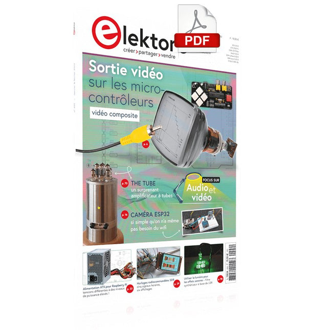
Le téléchargement intégral de ce numéro est disponible pour nos membres GOLD et GREEN sur le site Elektor Magazine !Pas encore membre ? Cliquez ici.Pour les yeux et les oreillessortie vidéo sur les microcontrôleurs (1)vidéo compositeelectronica 2022nouvelles du plus grand salon mondial de l'électroniquecaméra ESP32si simple qu'on n'a même pas besoin du wifialimentation ATX pour Raspberry Piamplificateur pour casque 32 Ωune solution simple mais de qualité à trois CIhorloges radiocommandées SDRcinq signaux horaires, six affichagesdémarrer en électroniquediodes spécialessur le viferrances qualitativesrétro-ingénierie d'un badge LED Bluetooth Low Energycomment commander un appareil BLE avec un script Pythonkit de développement MakePython ESP32tout dans une boîtemesure du THD avec un oscilloscope et une FFTcalculer facilement le facteur de distorsionmachines à vision totalela technologie derrière les systèmes de vision industrielle d'aujourd'huiInfographiesl'évolution de la commande vocale et audio des appareils électroniquesbilan du WEEF 2022bilan du salon electronica 2022les innovateurs n'ont pas manqué d'impressionnerThe Tubeun surprenant amplificateur à tubesà quand des biomatériaux pour l'électronique ?commutateur d'antenne Opera Cake pour HackRF Oneconnectez jusqu'à huit antennes à votre SDRconcevoir avec Arduino et plusentretien avec l'auteur Ashwin Pajankarjauge de longueur à lidarmesure jusqu'à 12 mles signaux audios et l'ESP32l'environnement ESP-ADF en pratiqueKit amplificateur de puissance Fortissimo-100 d'Elektorutiliser la lumière pour les effets sonoresfiltre synthétiseur à base de LDR, contrôlé en tension, 24 dB/octamplificateur Hi-Fi d'Elektorle plus bruyant de tous !visite à domicileafficheur volumétrique made in Canadaprojet 2.0corrections, mises à jour et courriers des lecteursHexadoku
€ 10,95
-
Elektor Digital Elektor Janvier/Février 2024 (PDF)
Le chargeur intégré est disponible pour nos clients OR et VERT sur le site d'Elektor Magazine ! Pas encore membre ? Cliquez ici . Comment fonctionne le projet : conception de la base énergétique pour l'ESP32 Prochaines étapes du prototypage optimisation des centrales solaires sur le balcon Considérations, faits et calculs ESP32 avec OpenDTU pour les centrales électriques sur le balcon Relever les données des petits onduleurs avec des microcontrôleurs alimentation linéaire variable Ensemble Alimentation 0-50 V / 0-2 A + alim symétrique double le stockage d'énergie aujourd'hui et dans le futur interview Simon Engelke 2024 : l'Odyssée de l'IA sans répétition Bluetooth LE sur le STM32 Plus que suffisant pour mesurer la distance boîte de conservation centre intelligent sur l'être humain MAUI : programmation pour PC, tablettes et smartphones le nouveau framework en théorie et en pratique ChatMagLev lévitation magnétique ? versionIA Régulateur de pulsation simple PV Réalisation du système de gestion de l'énergie photovoltaïque de base les composants à cathode froide sur le vif nostalgie démarrer en électronique ?Leçon FET tutoriel bus CAN pour l'Arduino UNO R4 deux UNO R4 connectés au bus infographie assistance complète en conception et développement les services d'ingénierie d'Arrow comparativement parlant, la force et l'efficacité de l'énergie condensateurs électrolytiques et aluminium sources potentielles de distorsions et technologie audio tester et mesurer l'USB le Fnirsi FNB58 l'outil Pick-and-Place manuel Pixel Pump simplifier l'assemblage du manuel des cartes CMS visite à domicile Naguère, dans un pays lointain ? « Dans le monde de l'éthique et de l'électronique, les petites choses sont faites avec un impact significatif. » éthique et électronique les orientations de l'OCDE et le soin apporté aux diligences impliquées dans la chaîne d'agrément Chadèche : chargeur/déchargeur intelligent pour accumulation NiMh résumé du projet de lecture projet 2.0 Corrections, mises à jour et courriers des lecteurs
€ 10,95
-
Elektor Digital Elektor Janvier/Février 2025 (PDF) FR
Le téléchargement intégral de ce numéro est disponible pour nos membres GOLD et GREEN sur le site Elektor Magazine ! Pas encore membre ? Cliquez ici. stockage de l’énergieRéalisez votre propre stockage d’énergie pour réseau de panneaux photovoltaïques simulateur de panneau solaireUne solution pour tester et optimiser les trackers MPP et les onduleurs le concours STM32 Edge AIDécouvrez le STM32N6 et gagnez les 5000 € du concours ! Matériaux à large bande interditePourquoi y a-t-il un tel intérêt pour le SiC et le GaN ? batterie externe pour ordinateur portableProlongez la durée de vie de votre vieil ordinateur portable robots médicauxSurmonter les obstacles techniques et réglementaires prévention du gel pour les vergersavec enregistrement des températures The Analog ThingL'Arduino de l’ordinateur analogique ? commande de relais à faible consommation d'énergieÉconomiser 90% de la puissance de commande amélioration de la charge DC ET5410A+pour un meilleur refroidissement et moins de bruit electronica 2024 : rétrospective compatibilité électromagnétiqueLa CEM en quelques mots ! démarrer en électronique......Filtres actifs réduisez les pertes des chutes de tension avec des condensateursprofitez astucieusement de la réactance capacitive le MCP4725 : un convertisseur numérique-analogique 12 bits pas cheravec une fonction EEPROM pour un comportement sûr au démarrage la pince de test intelligente Fnirsi LCR-ST1 pour CMS labo de test et de mesure personnel basé sur Raspberry PiPour commencer : l'ADC une charge électroniqueUn projet prêt à l'emploi 2025 : l'odyssée de l'IAQuelques projets pour le nouvel an AmpVolt v2.0 : mise à jour100 A et plus ! projet 2.0Corrections, mises à jour et courrier des lecteurs transparence éthiqueCe que révèle l’enquête réalisée par Ethics in Electronics carte Elektor Audio DSP FX Processor (2)Création d'applications
€ 10,95
-

Elektor Janvier/Février 2026 (FR)
Le téléchargement intégral de ce numéro est disponible pour nos membres GOLD et GREEN sur le site Elektor Magazine ! Pas encore membre ? Cliquez ici. alimentation de labo à très faible bruit (1)Une source silencieuse pour les circuits sensibles STM32 Edge AI Contest 2025 : les gagnants les batteries aujourd’huiTechnologies et différences entre les batteries au lithium charge électronique réglableCharge CC statique et dynamique convertisseur abaisseur de 48 V à 5 Vune réalisation pratique nœud de capteurs autonome v2.0Partie 2 : validation matérielle et optimisations énergétiques varistancesDrôles de composants, la série compteur graphique de fréquence du réseauSurveillance de la qualité du réseau démarrer en électronique…Touche à sa fin ferrites CMS à charge de courant de crêteplus résistantes aux pics de courant Elektor Live! Expert Day 2025 la récupération d’énergie propulse l’IoT et l’IIoT vers une nouvelle èreLa récupération d’énergie affranchit l’IoT de la dépendance au réseau Fnirsi DPS-150Alimentation portable compacte et convertisseur source d’alimentation USB-C réglableTransformez votre chargeur USB-C en alimentation réglable chargeur simple et testeur de capacitéAvec deux modules économiques « prêts à l’emploi » détecteur de couleurs intelligent avec synthèse vocale et lecture audio basées sur l’IA PbMonitor v2.0Présentation du système de surveillance de batteries mis à jour un ventilateur pour la mini-plaque de refusionDes modifications astucieuses pour des résultats optimisés sur le vifL’excès d’indulgence projet 2.0Corrections, mises à jour et courriel des lecteurs 2026 : une odyssée de l’IAQuand les modèles commencent à orienter le matériel picoampèremètre de précision (2)Assemblage, étalonnage et test alimentation sans fil des appareilsavec technologie inductive conduite autonome basée sur l’IALe Self Driving Challenge 2024 du RDW carte son comme générateur de signauxUn PC utilisé comme émetteur de test DCF77
€ 16,50
-

Elektor Digital Elektor Janvier/Février 2026 (PDF) FR
Le téléchargement intégral de ce numéro est disponible pour nos membres GOLD et GREEN sur le site Elektor Magazine ! Pas encore membre ? Cliquez ici. alimentation de labo à très faible bruit (1)Une source silencieuse pour les circuits sensibles STM32 Edge AI Contest 2025 : les gagnants les batteries aujourd’huiTechnologies et différences entre les batteries au lithium charge électronique réglableCharge CC statique et dynamique convertisseur abaisseur de 48 V à 5 Vune réalisation pratique nœud de capteurs autonome v2.0Partie 2 : validation matérielle et optimisations énergétiques varistancesDrôles de composants, la série compteur graphique de fréquence du réseauSurveillance de la qualité du réseau démarrer en électronique…Touche à sa fin ferrites CMS à charge de courant de crêteplus résistantes aux pics de courant Elektor Live! Expert Day 2025 la récupération d’énergie propulse l’IoT et l’IIoT vers une nouvelle èreLa récupération d’énergie affranchit l’IoT de la dépendance au réseau Fnirsi DPS-150Alimentation portable compacte et convertisseur source d’alimentation USB-C réglableTransformez votre chargeur USB-C en alimentation réglable chargeur simple et testeur de capacitéAvec deux modules économiques « prêts à l’emploi » détecteur de couleurs intelligent avec synthèse vocale et lecture audio basées sur l’IA PbMonitor v2.0Présentation du système de surveillance de batteries mis à jour un ventilateur pour la mini-plaque de refusionDes modifications astucieuses pour des résultats optimisés sur le vifL’excès d’indulgence projet 2.0Corrections, mises à jour et courriel des lecteurs 2026 : une odyssée de l’IAQuand les modèles commencent à orienter le matériel picoampèremètre de précision (2)Assemblage, étalonnage et test alimentation sans fil des appareilsavec technologie inductive conduite autonome basée sur l’IALe Self Driving Challenge 2024 du RDW carte son comme générateur de signauxUn PC utilisé comme émetteur de test DCF77
€ 10,95
-
Elektor Digital Elektor juillet/août 2020 (PDF)
ELEKTOR AIDE L'aide électronique quand ça va mal SYSTÈME PRIVÉ D'INFORMATION DOMESTIQUE Avec Windows sur Raspberry Pi PRIX ET PRINCIPAL LE NODE ROUGE Programmation de visuels en blocs à code overt, façon Lego® L'ÉTÉ GÉNÉREUX D'ELEKTOR Des dons pour les doués PETIT GÉNÉRATEUR DE FONCTIONS circulation du signal à contresens GREATSCOTT ! CONSTRUIRE UN SYSTEME D'ALARME LORA BANC D'ESSAI : ALIM DE LABO NUMÉRIQUE JOY-IT RD6006 ET KIT le 0 à 60 V et le 0 à 6 A BANC D'ESSAI : CARTE D'INTERFACE GREATFET ONE Farfouiller sous les jupes de l'USB... à cause de la gêne ? RETOUR DES PETITS CIRCUITS ? XXL Quelques bonnes petites pépites ANTENNE WI-FI 2.4 GHZ EXTERNE DU PAUVRE THERMOSTAT SIMPLE AVEC RASPBERRY PI COMMENTAIRE (BIEN) PHOTOGRAPHIER L'ÉLECTRONIQUE montrez vos montages sous leur meilleur jour BANC D'ESSAI : I²CDRIVER l'I²C passe par l'USB BANC D'ESSAI : ÉCRAN TACTILE PORTABLE JOY-VIEW 13 DE  JOIE-LE CONVERTISEUR ÉLÉVATEUR À LED POUR ?C Amusez-vous bien! LAVE-LINGE EXPÉRIMENTAL À ULTRASONS BANC D'ESSAI : GÉNÉRATEUR DE SIGNAUX JOY-IT JDS2915 2 voix + fréquencemètre FEUX TRICOLORES ET ASSEMBLEUR PIC CLIGNOTANT ÉTERNEL?EKTOR CAPTEUR À EFFET HALL EXPÉRIMENTAL DÉBUSQUER DES COURTS CIRCUITS À L'ESR-MÈTRE OU AU MILLI-OHMMÈTRE BANC D'ESSAI : KIT PRATIQUE ELEKTOR SDR La radio logicielle : loisir passionnant et chronophage DANSE LES TUYAUX KICK-STARTER ÉLECTRIQUE Hein ?, quelle est la prochaine étape ? AT-ON VRAIMENT BESOIN DE TOUT CE BAZAR ? Oui, car c'est la que je passe le plus clair de mon temps sur des projets électroniques REGARDER ÉLECTRONIQUE CINÉTIQUE Porte des étoiles chantournée BONJOUR LE MONDE! ELEKTOR EST ACTIF AUSSI SUR LES RÉSEAUX SOCIAUX M4 + 2XA7 + GPU : ÉQUIPE DE RÊVE OU PRESQUE ! Nouveau SoC STM32MP1 : pour exigences les plus élevées PORTE-PIC POUR 16F18877 ET AUTRES GROS PICS TRAFIC ENTRE ?C PAR LE BUS SPI ET L'ATMEGA328P SIX VARIANTES D'OSCILLATEURS ET LA CAPA DE MILLER MICRO OSCILLOSCOPE AVEC BBC MICRO:BIT AVEC POSTER À LED CHENILLARD KNIGHT RIDER AVEC L'ESP32 ATTINY13 EN GÉNÉ DE SIGNAUX MA POUR GO/PO DIP MÈTRE MINIMALISTE TROTTINETTE ÉLECTRIQUE BON MARCHÉ Que diriez-vous d'une trottinette homologuée vendue 300 ? par Lidl ? AIDE AU STATIONNEMENT EN MARCHE AR PAR ULTRASONS AVEC ARDUINO UNO PÉDALE DE DISTORSION À AMPLI OP ET TUBES L'ÉTABLI DE L'ÉLECTRONICIEN : L'ESSENTIEL HEXAD?KU ? CASSE-TÊTE POUR ÉLECTRICIENS INTELLIGENCE ARTIFICIELLE POUR DÉBUTANTS (2) Réseaux de neurones avec Linux et Python
€ 10,95
-
Elektor Digital Elektor juillet/août 2021 (PDF)
LORA AVEC LE RASPBERRY PI PICOS'amuser avec MicroPythonRISC-V : QUESACO ?Pourquoi une nouvelle architecture de noyau enthousiasme-t-elle l'industrie ?ELEKTOR @ 60Circuits of Summer PastMODULE D'ALIMENTATION POLYVALENT POUR PLAQUE D'EXPÉRIMENTATIONTensions positives et négatives grâce à un chargeur USB de 5 VRASPBERRY PI PICO ESSENTIALSExtrait : Wi-Fi avec le Raspberry Pi PicoLÉVITATION MAGNÉTIQUE SANS PEINEPROPELLER 2 DE PARALLAX (3)Faire clignoter une LEDPROGRAMMATION DES CARTES NUCLEO AVEC STM32CUBEIDEExtrait : FreeRTOS pour le MCU STM32EXTENSION DU MODULE CONVERTISSEUR ÉLÉVATEUR CC-CC MT3608Tips & Tricks, Best Practices and Other Useful InformationDT71 DE MINIWAREbrucelles de mesure numériquesGADGET WI-FI VESTIMENTAIREESPHome à nouveau à la manœuvre !DÉMARRER EN ÉLECTRONIQUE… (8)…est moins difficile qu'on ne l'imagine ! Les condensateurs : suite et finPETITS CIRCUITS AVEC L'ÉCOSYSTÈME QWIICJAVA SUR RASPBERRY PIPartie 2 : commande des broches GPIO avec un service REST de SpringRASPBERRY PI COMPUTE MODULE 4Un Raspberry Pi industrielMONITEUR DE LA QUALITÉ DE L'AIR, PORTABLE ET AUTONOME, POUR PARTICULES DE 2,5 ΜMGardez un œil sur votre santéSUR LE VIFLe futur était meilleur dans le passéMICROPYTHON POUR L'ESP32 ET SES COPAINSPartie 1 : installation et premiers programmesCOMPOSANTS À COUPLAGE DE CHARGE DANS LES OSCILLOSCOPESDrôle(s) de composant(s)ESD – LE DESTROYER FANTÔMEFoudroiement spontané des composantsÉNERGIE SOLAIRE POUR LES ROBOTS DE TONTEÉcologique, peu coûteux, simple !L'EUROPE TENTE DE DOMPTER LES GAFAHEXADOKUThe Original Elektorized Sudoku
€ 10,95
-
Elektor Digital Elektor juillet/août 2022 (PDF)
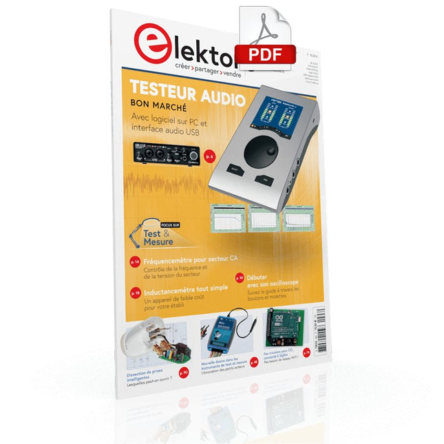
Testeur audio à prix modéré Et avec une base logique sur PC et une interface audio USB Fréquencemètre secteur CA Contrôler la fréquence et la tension du secteur Inductancemètre très simple Une tenue facile à porter Lévitation avec ondes acoustiques Un aperçu du kit de lévitation acoustique de Makerfabs Démarrer en électronique? Les redresseurs E-FFWD : regardons à nouveau vers l'avenir ! Débutant avec son oscilloscope Suivez le guide pour parcourir les boutons et molettes Radio logique MSF utilisant un Raspberry Pi Pico Décodeur à signal temporel à logique radio (SDR) basé sur le RPi Pico Capteurs d'humidité pour systèmes d'arrosage Arrosage automatique Nouvelle donne dans les instruments de test et mesure L'innovation des petits acteurs Infographie 07-08/2022 L?inspiration, c?est ça qui compte Entretien avec Walter Arkesteijn, l'entreprise InnoFaith Beauty Sciences et lecteur d'Elektor Minimiser les interférences CEM même avec le stockage Création d'interfaces graphiques et Python avec guide : Jeu de Morpion Relais Reed Drôles de composants ESR-mètre analogique simple et précis en galvanomètre en cadre mobile Feu tricolore pour CO2, connecté à Sigfox N'oubliez pas de vérifier le WiFi ! Femmes de technologie « On juge au mérite, jusqu'à ce que le mérite ait des seins. » Tablette oscilloscope ADS1013D à petit prix Bon rapport qualité/prix ? Dissection des prix intelligents Lesquelles peut-on ouvrir ? Impédance et capacité de la peau Petites expériences Sur le vif Nul n'est prophète en son pays Prise en main du Pokit Meter Couteau suisse pour la mesure Hexadoku Casse-tête pour électriciens
€ 10,95
-
Elektor Digital Elektor juillet/août 2023 (PDF)
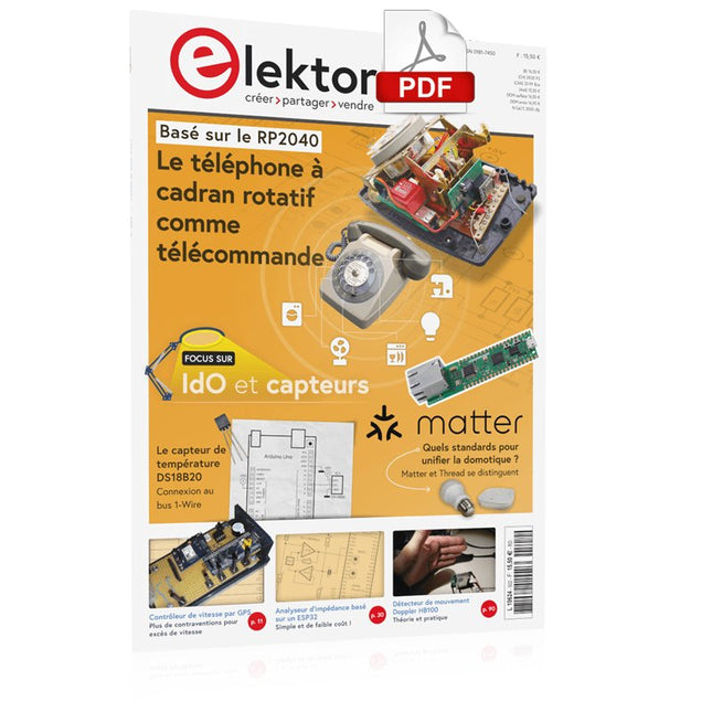
Le chargeur intégré est disponible pour nos clients OR et VERT sur le site d'Elektor Magazine ! Pas encore membre ? Cliquez ici . le téléphone à cadran rotatif comme télécommande pour allumer la lumière, composez le 1 ; verser la cafetière, composer les 2 régulateur de vitesse par GPS plus les contraventions pour excès de vitesse stroboscope RVB avec Arduino un instrument utile, instructif et désorientant bouton poussoir d'urgence sans fil sécuriser la force de location avec LoRa démarrer en électronique ...l'émetteur-suiveur comparateur à hystérésis à levelx indépendants simulations, calcul et algèbre analyseur basé sur un ESP32 simple, compatible avec les compositions et le faible coût ?! visite à domicile encouragez-nous pour les réalisations du personnel Carte d'apprentissage MCCAB pour Arduino Nano plateforme pour le cours « Cours pratique sur les microcontrôleurs ? sur le vif Luddisme moderne Babacapteur : le capteur de température DS18B20 connexion au bus 1-Wire quelles normes pour unifier la domotique ?? Matter et Thread se distinguent La matière, ou la concorde des objets Testez Matter avec la carte Thing Plus Matter et Simplicity Studio Infographie : IdO et capteurs Matière, ExpressLink, Rainmaker ? de quoi s'agit-il ? questions et réponses d'Amey Inamdar, directeur technique marketing chez Espressif introduction à la sélection de kits de développement de microcontrôleurs pour les applications IoT et IIoT un condensateur n?est pas toujours capacitif?! regarder NTP et CircuitPython pour l'utilisation du programme ? construire une simple sympathie IdO avec le Phambili Newt Détecteur de mouvement Doppler HB100 Théorie et pratique Guider la programmation bare-metal pour STM32 et autres microcontrôleurs revue multimètre Siglent SDM3045X microprocesseurs pour systèmes d'embarquement drôle de composants, la série la documentation des microcontrôleurs sans peine (3) schémas de principe, et autres documents station avec LoRa à faible puissance réaliser, même avec une gare avec un port long Transverter pour la bande 70 cm Ingénieurs appelant au climat Avancez vite et réparez les choses Hexadoku
€ 10,95
-
Elektor Digital Elektor Juillet/Août 2024 (PDF)
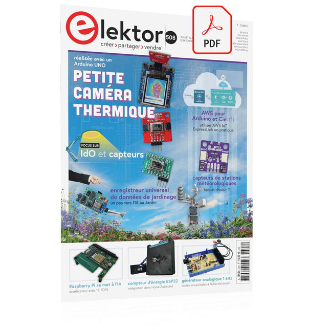
Le téléchargement intégral de ce numéro est disponible pour nos membres GOLD et GREEN sur le site Elektor Magazine ! Pas encore membre ? Cliquez ici. petite caméra thermiqueréalisée avec un Arduino UNO mise à jour du projet #3 : compteur d'énergie basé sur l'ESP32intégration et test avec Home Assistant 2024 : l'odyssée de l'IAaméliorer la détection d'objets : intégration de techniques avancées Raspberry Pi se met à l'IAun nouveau kit comprenant un accélérateur IA matériel et un adaptateur M.2 HAT+ capteurs de stations météorologiqueslequel choisir ? Relevé des compteurs d'eau basé sur l'IA (1)intégrez votre ancien compteur dans l'IdO ! une alarme GSMun module GSM protège votre garage à distance optimisation et contrôle des appareils Thread à faible consommation d'énergiefaible consommation... peu d’effort ? sur le vifmontrez-moi là où ça fait mâle chambre à brouillard à faire soi-mêmevisualiser les rayonnements invisibles SparkFun Thing Plus Mattercarte de développement IdO polyvalente basée sur Matter Rétroéquipement IoTAdaptation des machines à interface RS232 à l'industrie 4.0 ajouter l’IoT grâce aux microcontrôleurs 8 bits la technologie au service du développement durableles avancées technologiques favorisent une utilisation plus efficace de l’énergie dans de nombreuses applications AWS pour Arduino et Cie. (1)utiliser AWS IoT ExpressLink en pratique détecteur de flux d'air Arduinoaucun capteur externe n'est nécessaire ! détecteur de fuite d'eauconnecté à l’Arduino Cloud le quartzdrôle de composant, la série enregistreur universel de données de jardinageun pas vers l’Intelligence Artificielle au Jardin. un générateur analogique 1 kHzondes sinusoïdales à faible distorsion Miletus : utiliser les applications Web hors ligneaccès aux fonctions de l’appareil et du système de la 4G à la 5Gest-ce une étape si facile à franchir ? démarrer en électronique…connexions symétriques
€ 10,95
-
Elektor Juillet/Août 2025 (FR)
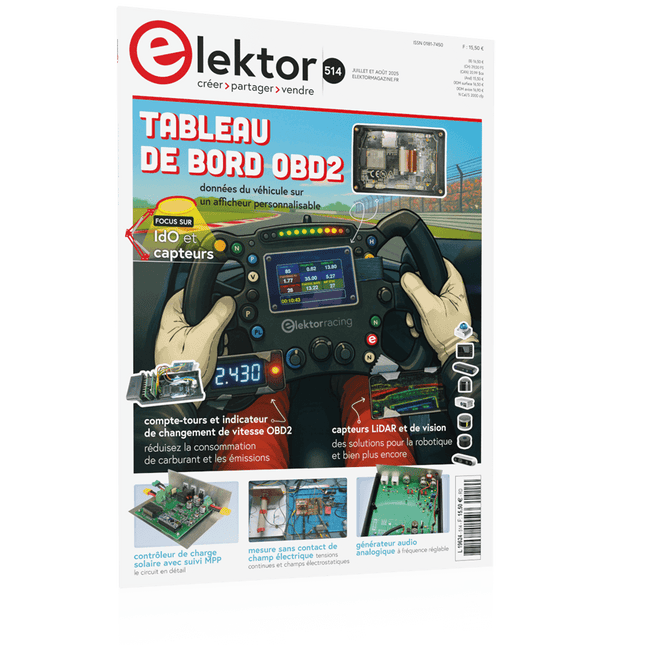
Le téléchargement intégral de ce numéro est disponible pour nos membres GOLD et GREEN sur le site Elektor Magazine ! Pas encore membre ? Cliquez ici. tableau de bord OBD2Des cadrans anciens aux données en temps réel OBD2 : ajoutez un compte-tours et un indicateur de changement de vitesse à votre voitureRétro, mais extrêmement utile capteurs de vision et LiDAR pour la robotique Sensor+Test 2025 et PCIM 2025 mesures sans contact du champ électrique (1)Membrane vibrante pour mesurer des tensions continues ou des champs électriques statiques détecteur de courrier sans filCapteurs optiques, radars… quelques options à explorer Elektor Mini-WheelieUn robot auto-équilibré cellules solairesDrôles de composants, la série premiers pas avec un capteur radar moderneUn capteur précis qui ne passe pas inaperçu sur le vifUsine de papier CybersécuritéDes temps difficiles pour les hackers Infographie : IdO et capteurs le Bluetooth 6.0 pour des applications de télémétrie amélioréesCette nouvelle version offre des fonctions de localisation améliorées découvrez la communication sans fil avec BeagleY-AI Projet 2.0Corrections, mises à jour et courrier des lecteurs démarrer en électronique……Conclusion sur les ampli-op un puissant assistant de codage de l'IAAccélérez votre développement avec Continue et Visual Studio Code contrôleur de charge solaire avec MPPT (2)Le circuit détecteur d'obstacles à ultrasonsUn projet simple pour aider les malvoyants une odyssée de l'IABilan du premier semestre synthétiseur MIDI autonome Raspberry Pi (3)plus intelligent avec une interface utilisateur Meshtastic : un projet de démoUn réseau intelligent de noeuds LoRa générateur analogique de fréquences audioGénérateur de signaux sinusoïdaux de haute qualité à fréquence réglable
€ 15,50


