Produits
-
Elektor Septembre/Octobre 2025 (FR)
Le téléchargement intégral de ce numéro est disponible pour nos membres GOLD et GREEN sur le site Elektor Magazine ! Pas encore membre ? Cliquez ici. carte émetteur-récepteur audio ESP32 (2)Transmission audio sans fil émetteur AM par inductionUtiliser les PIO du Pico dans un croquis Arduino les protocoles sans filUn guide technique suivi de satellites avec LoRaTinyGS, le réseau open source qui capte les données spatiales télécommande par sms compatible 4GContrôlez votre équipement à distance sonde haute vitesseMesure à haute impédance jusqu’à 200 MHz sur le vifKafka KrakenSDR tests de performance avec le RP2350Pico 2 : une vraie amélioration ? mesures de champ électrique sans contact (2)Un vibromètre laser pour l’analyse des vibrations de la membrane quartz et oscillateursAméliorer la précision des quartz grâce au choix des condensateurs démarrer en électroniqueCI audio originaux se lancer dans le codage d'un projet DIY SPECTRAN® V6 MobileAnalyseur de spectre temps réel modulaire et configurable pour des mesures fiables sur l’ensemble des plages de fréquences l’avenir de l’IA repose sur le siliciumEntretien avec Anastasiia Nosova nœud de capteurs autonome v2.0 (architecture du système)Plateforme de mesure autonome alimentée par énergie solaire, avec GPS intégré, LoRaWAN et plus encore positionnement précisTests du sondage de canal Bluetooth développement logiciel piloté par les tests voiture miniature contrôlée par SmartphoneWi-Fi + ESP32 + Smartphone = contrôle à distance 2025 : une odyssée de l’IAModèles de raisonnement en IA : la révolution de la chaîne de pensée contrôleur de charge solaire avec MPPT (3)Logiciel et mise en service caméra Web Raspberry Pi ZeroStreaming avec VPN ZeroTier
€ 15,50
-
Elektor Digital Elektor Septembre/Octobre 2025 (PDF) FR
Le téléchargement intégral de ce numéro est disponible pour nos membres GOLD et GREEN sur le site Elektor Magazine ! Pas encore membre ? Cliquez ici. carte émetteur-récepteur audio ESP32 (2)Transmission audio sans fil émetteur AM par inductionUtiliser les PIO du Pico dans un croquis Arduino les protocoles sans filUn guide technique suivi de satellites avec LoRaTinyGS, le réseau open source qui capte les données spatiales télécommande par sms compatible 4GContrôlez votre équipement à distance sonde haute vitesseMesure à haute impédance jusqu’à 200 MHz sur le vifKafka KrakenSDR tests de performance avec le RP2350Pico 2 : une vraie amélioration ? mesures de champ électrique sans contact (2)Un vibromètre laser pour l’analyse des vibrations de la membrane quartz et oscillateursAméliorer la précision des quartz grâce au choix des condensateurs démarrer en électroniqueCI audio originaux se lancer dans le codage d'un projet DIY SPECTRAN® V6 MobileAnalyseur de spectre temps réel modulaire et configurable pour des mesures fiables sur l’ensemble des plages de fréquences l’avenir de l’IA repose sur le siliciumEntretien avec Anastasiia Nosova nœud de capteurs autonome v2.0 (architecture du système)Plateforme de mesure autonome alimentée par énergie solaire, avec GPS intégré, LoRaWAN et plus encore positionnement précisTests du sondage de canal Bluetooth développement logiciel piloté par les tests voiture miniature contrôlée par SmartphoneWi-Fi + ESP32 + Smartphone = contrôle à distance 2025 : une odyssée de l’IAModèles de raisonnement en IA : la révolution de la chaîne de pensée contrôleur de charge solaire avec MPPT (3)Logiciel et mise en service caméra Web Raspberry Pi ZeroStreaming avec VPN ZeroTier
€ 10,95
-

Elektor Digital Elektor Special: Power Supplies and Batteries (PDF)
Quelles que soient les méthodes ou même les moyens financiers dont vous disposez pour faire fonctionner vos circuits, l'alimentation électrique doit figurer en bonne place, voire numéro un, dans vos considérations. Le bloc de conception simplement appelé « alimentation » est extrêmement sous-estimé, tant dans la création que dans la réparation de produits électroniques. Pourtant, le « PSU » présente une énorme diversité et se présente sous des formes très différentes comme AC/DC, générateur, batterie (rechargeable ou non), panneau photovoltaïque, de table, linéaire ou à découpage, pour n'en citer que quelques-uns. Les plages de sortie sont également stupéfiantes, du nano-ampère au kiloampère et il en va de même pour les tensions. Ce spécial couvre les caractéristiques et les aspects de conception des alimentations. Contenu Les bases Gestion de la batterie Ce qu'il faut savoir lors de l'utilisation de piles (au lithium). Alimentation à tension fixe utilisant des régulateurs linéaires Le meilleur résultat juste après les piles. Récupération d'énergie lumineuse Un petit panneau solaire est utilisé dans un projet de récupération d'énergie pour gérer et charger quatre cellules AAA. Conception de l'adaptateur alimenté par secteur Circuits de base et conseils pour transformateurs, redressement, filtrage et stabilisation. Démarrage progressif LM317 L'impulsion de courant d'appel élevée doit être évitée. Redresseurs contrôlables Quelques suggestions pour maintenir la perte de puissance dans le régulateur linéaire aussi faible que possible. Composants Feuille de travail : Les régulateurs de tension LM117 / LM217 / LM317 Supercapsules Basse tension mais beaucoup de courant… ou pas ? Commentaires Kit d'alimentation de table JOY-iT RD6006 Charge électronique CC programmable Siglent SDL1020X Projets Centrale électrique du balcon Balcon solaire DIY = retour sur investissement rapide ! Kit de compresseur LiPo DIY De l'artisanat au marché de masse Thyristor MOSFET à double anode Plus rapide et moins coûteux que l'ancien SCR Presse-agrumes à batterie Ne jetez pas, pressez ! Alimentation haute tension avec traceur de courbe Générez des tensions jusqu'à 400 V et tracez des courbes caractéristiques pour les vannes et les transistors Alimentation haute tension pour RIAA Pour préamplis à lampes RIAA et autres applications. MicroApprovisionnement Une alimentation de laboratoire pour les appareils connectés Alimentation fantôme utilisant des condensateurs commutés Tripleur de tension utilisant trois circuits intégrés L'alimentation à découpage SMPS800RE pour l'Elektor Fortissimo-100 Fiable, léger et abordable Démarrage progressif pour bloc d'alimentation Soyez gentil avec votre alimentation – et sa charge UniLab 2 Alimentation de laboratoire compacte à découpage 0-30 V, 3 A Conseils Démarrage progressif pour les régulateurs à découpage abaisseurs Limite de courant de perte faible Batterie externe Surprise Un terrain virtuel Mainteneur de batterie Déchargeur de batterie Connexion des régulateurs de tension en parallèle
€ 11,95
Membres : € 10,76
-
Elektor Digital Elektor Special: Raspberry Pi and Pico (PDF)
Contents Projects PicoVoiceVoice alienation and sound effects with the Raspberry Pi Pico Navigation with Vibration Feedback POV Display Pulse Width Modulation (PWM) with the Raspberry Pi Pico Wi-Fi with the Raspberry Pi Pico 'Hello World' from the Raspberry Pi Pico and RP2040A look at the Raspberry Pi Foundation’s first microcontroller Simple On-Off Temperature Controller with Raspberry Pi HAT Multitasking with the Raspberry PiShowcase: a traffic lights controller The Raspberry Pi Ruler GadgetFun with a time-of-flight sensor Raspberry Pi Buffer Board (Mk. 1)Never blow up the I/O again FM radio with RDSA top HAT project for the Raspberry Pi LoRa with the Raspberry Pi PicoFun with MicroPython! Tutorials Qt for the Raspberry Pi Raspberry Pi Pico Programmingwith MicroPython and Thonny Raspberry Pi Full StackRPi and RF24 at the heart of a sensor network Raspberry Pi Bash Command Cheat Sheet Community Java on the Raspberry PiAn interview with Frank Delporte Reviews Introducing the New Raspberry Pi Pico W, H, and WH Secure Boot Solution for Raspberry PiRetrofit security at a reasonable price Review: SmartPi – Smart Meter Extension for Raspberry Pi Review: The Enviro+ Raspberry Pi HATMeasuring environmental data with Raspberry Pi and the HAT Enviro+ Review: Meet the Raspberry Pi 4All new but still good? Raspberry Pi Gets a Fast 3.5' Touch DisplayMore power at no extra charge Book Launch: Raspberry Pi for Radio Amateurs
€ 11,95
Membres : € 10,76
-

Elektor Special: Robotics and Automation
AI in Practice Dive into the fascinating world of robotics and automation! This Elektor Special shows you how to build your own robots with creativity, a little know-how, and affordable technology. From your first DIY project with Arduino or Raspberry Pi to intelligent systems with AI – this issue makes modern robotics understandable and accessible. Discover practical instructions, inspiring projects, and exciting insights into the maker scene. Learn how experimentation, community, and openness give rise to true innovation – and why robotics is so much more than just a technical hobby. Contents Imagination turns into reality Arduino-controlled Drawing Robot GalaxyRVR Mars Rover Kit for Arduino YDLIDAR X4Pro Lidar xHuskyLens AI Camera DOF Robot Arm with Raspberry Pi Pico Manufacturing Robots with Fischertechnik Pneumatic Industrial Robot Why Do We Keep Building Robot Dogs? Elektor Mini-Wheelie Robot Vehicles and Autonomous Driving
€ 19,95
Membres : € 17,96
-

Elektor Digital Elektor Special: Robotics and Automation (PDF)
AI in Practice Dive into the fascinating world of robotics and automation! This Elektor Special shows you how to build your own robots with creativity, a little know-how, and affordable technology. From your first DIY project with Arduino or Raspberry Pi to intelligent systems with AI – this issue makes modern robotics understandable and accessible. Discover practical instructions, inspiring projects, and exciting insights into the maker scene. Learn how experimentation, community, and openness give rise to true innovation – and why robotics is so much more than just a technical hobby. Contents Imagination turns into reality Arduino-controlled Drawing Robot GalaxyRVR Mars Rover Kit for Arduino YDLIDAR X4Pro Lidar xHuskyLens AI Camera DOF Robot Arm with Raspberry Pi Pico Manufacturing Robots with Fischertechnik Pneumatic Industrial Robot Why Do We Keep Building Robot Dogs? Elektor Mini-Wheelie Robot Vehicles and Autonomous Driving
€ 14,95
Membres : € 13,46
-
Elektor Special: Solar Power Systems and Photovoltaics
As demand for solar panel installation has risen sharply, especially for installations larger than balcony power plants, the order books of solar companies are full. If you ask for a quote today, you may have to wait a while, if your request isn't simply postponed indefinitely. Another consequence of the solar boom is that some companies are charging very high prices for installations. Yet there is an obvious and radical solution to the problem of excessive prices: Do it yourself, as the English say. The price of materials is currently affordable, and it's the ideal time for those who do the work themselves. They couldn't save more. Add to this the satisfaction of doing something useful, both economically and ecologically, and the pleasure of building yourself. In this special issue, you'll find a wide selection of Elektor assemblies, from solar panel controllers to solar water heaters and solar panel orientation systems. The issue also contains practical information on solar panel installation and the technology behind them. Finally, there are a number of articles on the subject of balcony power plants, from how to install them to how to connect them to the Internet... Contents BASICS Dimensioning Photovoltaic Panel ArraysAn introduction to photovoltaic energy and the commonest techniques,followed by simplified calculation models and setup guidelines. Light Sensor TechnologyMeasuring daylight using LEDs. Solar Power Made SimpleSolar charging with and without a controller. Cable Cross-sections and Energy Losses in Solar SystemsKey considerations on the minimum values to respect for electricalcurrent in solar panel cabling. Solar ModulesEverything you always wanted to know about solar panels... Ideal Diode ControllerDiode Circuits with Low Power Dissipation. TIPS Tracking for Solar Modules zBot Solar/Battery Power Supply Solar Cell Array Charger with Regulator Solar Cell Voltage Regulator Solar-Powered Night Light Alternative Solar Battery Charger PROJECTS Energy LoggerMeasuring and Recording Power Consumption. Tiny Solar SupplySunlight In, 3.3 V Out. A Do-It-Yourself DTURead Data from Small Inverters by μC. Solar ChargerPortable energy for people on the move. Solar Thermal Energy RegulatorMaximum power point tracking explored. 2-amp Maximum Power Tracking ChargerSolar Power To The Max. Computer-driven HeliostatFollow the sun or the stars. Garden LightingUsing solar cells. Solar Panel Voltage Converter for IoT DevicesYes we CAN exploit indoor lighting. Travel ChargerFree power in the mountains. Solar Cell Battery Charger/MonitorWith protection against deep discharge. Solar-powered Battery ChargerPIC12C671 avoids overcharging and deep charging. Converters for Photovoltaic PanelsContributed by TME (Transfer MultisortElektronik). Solar Charging RegulatorFor panels up to 53 watts. Solar-Powered ChargerFor lead-acid batteries. CAN Bus + Arduino for Solar PV Cell MonitoringDetect and locate serviceable panels in large arrays. Balcony Power Plant 2.0The latest: solar panels, installation and inverters
€ 19,95
Membres : € 17,96
-
Elektor Digital Elektor Special: Solar Power Systems and Photovoltaics (PDF)
As demand for solar panel installation has risen sharply, especially for installations larger than balcony power plants, the order books of solar companies are full. If you ask for a quote today, you may have to wait a while, if your request isn't simply postponed indefinitely. Another consequence of the solar boom is that some companies are charging very high prices for installations. Yet there is an obvious and radical solution to the problem of excessive prices: Do it yourself, as the English say. The price of materials is currently affordable, and it's the ideal time for those who do the work themselves. They couldn't save more. Add to this the satisfaction of doing something useful, both economically and ecologically, and the pleasure of building yourself. In this special issue, you'll find a wide selection of Elektor assemblies, from solar panel controllers to solar water heaters and solar panel orientation systems. The issue also contains practical information on solar panel installation and the technology behind them. Finally, there are a number of articles on the subject of balcony power plants, from how to install them to how to connect them to the Internet... Contents BASICS Dimensioning Photovoltaic Panel ArraysAn introduction to photovoltaic energy and the commonest techniques,followed by simplified calculation models and setup guidelines. Light Sensor TechnologyMeasuring daylight using LEDs. Solar Power Made SimpleSolar charging with and without a controller. Cable Cross-sections and Energy Losses in Solar SystemsKey considerations on the minimum values to respect for electricalcurrent in solar panel cabling. Solar ModulesEverything you always wanted to know about solar panels... Ideal Diode ControllerDiode Circuits with Low Power Dissipation. TIPS Tracking for Solar Modules zBot Solar/Battery Power Supply Solar Cell Array Charger with Regulator Solar Cell Voltage Regulator Solar-Powered Night Light Alternative Solar Battery Charger PROJECTS Energy LoggerMeasuring and Recording Power Consumption. Tiny Solar SupplySunlight In, 3.3 V Out. A Do-It-Yourself DTURead Data from Small Inverters by μC. Solar ChargerPortable energy for people on the move. Solar Thermal Energy RegulatorMaximum power point tracking explored. 2-amp Maximum Power Tracking ChargerSolar Power To The Max. Computer-driven HeliostatFollow the sun or the stars. Garden LightingUsing solar cells. Solar Panel Voltage Converter for IoT DevicesYes we CAN exploit indoor lighting. Travel ChargerFree power in the mountains. Solar Cell Battery Charger/MonitorWith protection against deep discharge. Solar-powered Battery ChargerPIC12C671 avoids overcharging and deep charging. Converters for Photovoltaic PanelsContributed by TME (Transfer MultisortElektronik). Solar Charging RegulatorFor panels up to 53 watts. Solar-Powered ChargerFor lead-acid batteries. CAN Bus + Arduino for Solar PV Cell MonitoringDetect and locate serviceable panels in large arrays. Balcony Power Plant 2.0The latest: solar panels, installation and inverters
€ 14,95
Membres : € 13,46
-
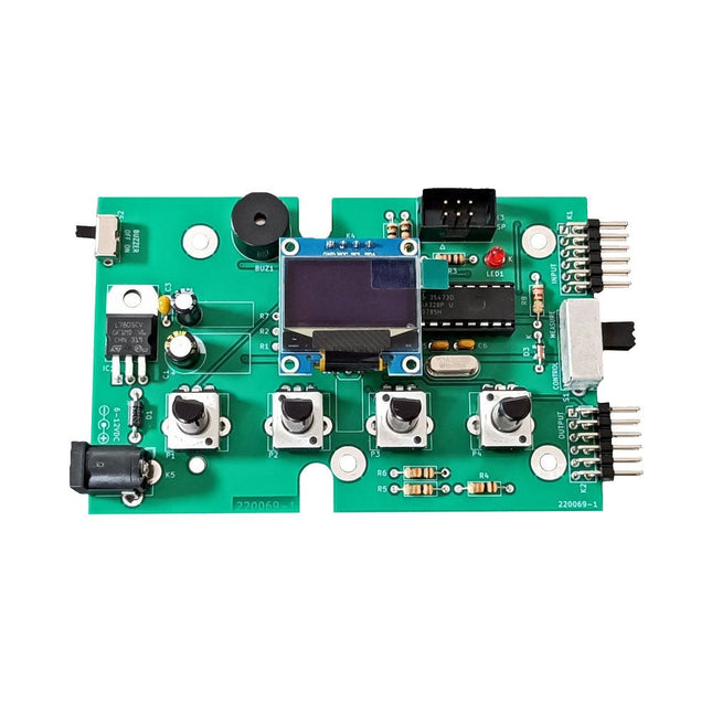
Elektor Labs Kit de test Super Servo Elektor
Le kit de test Super Servo Elektor permet le contrôle des servomoteurs et la mesure de leurs signaux. Il permet le test simultané de quatre servomoteurs. Le testeur est fourni en kit. Tous les composants nécessaires à l'assemblage du dispositif sont fournis dans le kit. Une expérience basique de soudure électronique est nécessaire pour réaliser l'assemblage du kit. Le microcontrôleur est préprogrammé. Le testeur Super Servo est doté de deux modes de fonctionnement: Control/Manual et Measure/Inputs : Dans le mode Control/Manual, le Testeur Super Servo délivre à ses sorties , les signaux de contrôle pour quatre servomoteurs, ou pour un contrôleur de vol ou un contrôleur de vitesse ESC (Electronic Speed Controller) pour moteur sans balai (brushless). Les signaux sont contrôlés par quatre potentiomètres. Dans le mode Measure/Inputs le Testeur Super Servo mesure les signaux des servomoteurs reliés à ses entrées. Ces signaux peuvent par exemple provenir d'un ESC, d'un contrôleur de vol, d'un récepteur ou de tout autre dispositif. Les signaux sont également dirigés vers ses sorties afin de contrôler les servomoteurs, l'ESC ou le contrôleur de vol. Les résultats sont visualisés sur l'écran. Spécifications Modes de fonctionnement Control/Manual et Measure/Inputs (Contrôle manuel et mesures) Nombre de canaux 3 Entrées des signaux des servomoteurs 4 Sorties des signaux vers les servomoteurs 4 Alarme Buzzer & LED Affichage Écran OLED de 0,96' (128 x 32 pixels) Tension d'entrée K5 7-12 V CC Tension d'entrée K1 5-7,5 V CC Courant d'entrée 30 mA (9 VDC sur K5, K1 et K2 non reliés) Dimensions 113 x 66 x 25 mm Poids 60 g Inclus Résistances (0,25 W) R1, R3 1 kΩ, 5% R2, R4, R5, R6, R7, R9, R10 10 kΩ, 5% R8 22 Ω, 5% P1, P2, P3, P4 10 kΩ, potentiomètre vertical linéaire/B Condensateurs C1 100 µF 16 V C2 10 µF 25 V C3, C4, C7 100 nF C5, C6 22 pF Semiconducteurs D1 1N5817 D2 LM385Z-2.5 D3 BZX79-C5V1 IC1 7805 IC2 ATmega328P-PU, programmé LED1 LED, 3 mm, rouge T1 2N7000 Divers BUZ1 Buzzer Piezo avec oscillateur K1, K2 Connecteur à 2 rangées de 12 broches à 90° K5 Connecteur jack K4 Connecteur à 1 rangée de 4 broches K3 Connecteur à 2 rangées de 6 broches S1 Interrupteur à glissière 2P2T S2 Interrupteur à glissière 1P2T X1 Quartz, 16 MHz Support DIP 28 broches pour IC2 Circuit imprimé Elektor Afficheur OLED de 0,96', 128 x 32 pixels, interface I²C à 4 broches Liens Elektor Magazine Elektor Labs
€ 59,95€ 49,95
Meilleur prix
-

Elektor Classics Archives d'Elex sur clé USB
Les mots-clés du magazine ELEX publié par Elektor sont ÉLECTRONIQUE – EXPÉRIMENTATION – EXPLORATION. L'électronique est une discipline originale qui consacre l'essentiel de ses efforts à se perfectionner elle-même, mais la connaissance de ses principes et de ses fondements reste cruciale. L'expérimentation est fondamentale aussi, parce que c'est le goût de la manipulation qui, un jour lointain, de chiffons mouillés et de quelques plaques de métal a fait la première pile électrique. L'exploration, parce que pour guider l'expérimentation, il y a la passion de l'inconnu, la soif de comprendre, l’obstination, le sens de l'effort (souvent) gratuit. Tout ce qui fait la différence entre passion et indifférence. ELEX c'est : Rési & Transi (deux personnages d’une géniale bande dessinée d'initiation à l’électronique) mais aussi les rubriques Analogique Anti-Choc, Logique sans hic ou encore Mesure & Labo. Ce sont aussi des centaines de réalisations (audio, auto & moto & vélo, maison, jeux, bruitage, mini-circuits, modélisme, photo, radio & HF) etc. Bonus vidéo sur cette clé USB : 'Rési et Transi dans La conquête de l'électronique', un film de quatre épisodes autour de la réalisation d'un mini-orgue électronique.
-
Elektor Digital Embedded in Embedded (E-book)
ARM Cortex-M Embedded Design from 0 to 1 Hobbyists can mash together amazing functional systems using platforms like Arduino or Raspberry Pi, but it is imperative that engineers and product designers understand the foundational knowledge of embedded design. There are very few resources available that describe the thinking, strategies, and processes to take an idea through hardware design and low-level driver development, and successfully build a complete embedded system. Many engineers end up learning the hard way, or never really learn at all. ARM processors are essentially ubiquitous in embedded systems. Design engineers building novel devices must understand the fundamentals of these systems and be able to break down large, complicated ideas into manageable pieces. Successful product development means traversing a huge amount of documentation to understand how to accomplish what you need, then put everything together to create a robust system that will reliably operate and be maintainable for years to come. This book is a case study in embedded design including discussion of the hardware, processor initialization, low‑level driver development, and application interface design for a product. Though we describe this through a specific application of a Cortex-M3 development board, our mission is to help the reader build foundational skills critical to being an excellent product developer. The completed development board is available to maximize the impact of this book, and the working platform that you create can then be used as a base for further development and learning. The Embedded in Embedded program is about teaching fundamental skill sets to help engineers build a solid foundation of knowledge that can be applied in any design environment. With nearly 20 years of experience in the industry, the author communicates the critical skill development that is demanded by companies and essential to successful design. This book is as much about building a great design process, critical thinking, and even social considerations important to developers as it is about technical hardware and firmware design. Downloads EiE Software Archive (200 MB) IAR ARM 8.10.1 (Recommended IDE version to use) (1.2 GB) IAR ARM 7.20.1 (Optional IDE version to use) (600 MB)
€ 44,95
Membres : € 40,46
-
Elektor Digital Embedded Operating System (E-book)
History and Future in the Internet of Things This book thoroughly reviews the history of the development of embedded Operating Systems, covers the technical characteristics, historic facts, as well as background business stories of mainstream embedded Operating Systems, and analyzes the technical evolution, market development, and new opportunities of embedded Operating Systems in the age of the Internet of Things. From the perspective of time, the book examines the evolution of critical technical aspects, including real-time and Power Management of embedded Operating Systems and Linux, Internet of Things security, communication, and cloud computing. The book looks into applications of embedded Operating Systems with important markets of mobile phones, communication equipment, automobile, and wearable devices, and also discusses business model and the issue of intellectual property of embedded Operating Systems. In addition, the book walks through the status quo, technical features, product evaluation and background of the Internet of Things Operating Systems in the second half of the book.
€ 29,95
Membres : € 26,96
-

Elektor Publishing ESP32 by Example
A Project-Based Introduction to Microcontrollers and Drone Control A Practical Introduction to Embedded Systems with the ESP32 This book is intended for readers who are new to embedded systems and looking for a structured, example-driven way to begin. If you’ve explored general-purpose electronics or Arduino-based resources but found them too broad or lacking in practical application, this guide offers a more focused alternative. With a small, affordable set of components – such as LEDs, sensors, an OLED screen and a motion sensor – you’ll build and work with the same hardware setup throughout the book. This allows you to focus on learning and experimenting without constant reconfiguration. Topics include: Understanding and programming the ESP32 microcontroller Using the Arduino IDE to write and deploy code Exploring cyber-physical systems, culminating in basic drone control No prior experience with Arduino or embedded development is required. Each section includes hands-on examples and mini-projects designed to reinforce core concepts and encourage deeper exploration. By the end, you’ll be equipped not only to reproduce the book’s examples, but also to extend them toward your own ideas and applications. Whether your interest is in learning embedded programming, building interactive systems, or exploring educational drone control, this book provides a clear and practical path to getting started.
€ 44,95
Membres : € 40,46
-

Elektor Digital ESP32 by Example (E-book)
A Project-Based Introduction to Microcontrollers and Drone Control A Practical Introduction to Embedded Systems with the ESP32 This book is intended for readers who are new to embedded systems and looking for a structured, example-driven way to begin. If you’ve explored general-purpose electronics or Arduino-based resources but found them too broad or lacking in practical application, this guide offers a more focused alternative. With a small, affordable set of components – such as LEDs, sensors, an OLED screen and a motion sensor – you’ll build and work with the same hardware setup throughout the book. This allows you to focus on learning and experimenting without constant reconfiguration. Topics include: Understanding and programming the ESP32 microcontroller Using the Arduino IDE to write and deploy code Exploring cyber-physical systems, culminating in basic drone control No prior experience with Arduino or embedded development is required. Each section includes hands-on examples and mini-projects designed to reinforce core concepts and encourage deeper exploration. By the end, you’ll be equipped not only to reproduce the book’s examples, but also to extend them toward your own ideas and applications. Whether your interest is in learning embedded programming, building interactive systems, or exploring educational drone control, this book provides a clear and practical path to getting started.
€ 34,95
Membres : € 31,46
-

Elektor Academy Pro ESP32 by Example (Cours d'apprentissage)
Cours complet sur le microcontrôleur ESP32, comprenant une carte d’extension MCU spécialement conçue, des projets pratiques et un guide en ligne complet – idéal pour apprendre le matériel, la programmation et la connectivité étape par étape. Introduction pratique aux systèmes embarqués avec l'ESP32 Ce cours est conçu pour les débutants en systèmes embarqués qui recherchent une approche structurée et concrète pour se lancer. Si vous avez déjà exploré l'électronique générale ou les ressources basées sur Arduino, mais que vous les avez trouvées trop générales ou manquant de conseils pratiques, ce cours offre une alternative plus ciblée. Grâce au kit « ESP32 by Example » (EEK) – un ensemble de composants compacts et abordables comprenant des LED, des capteurs, un écran OLED et un processeur de mouvement – vous travaillerez avec une configuration matérielle cohérente tout au long du cours. Une fois assemblé, l'EEK reste quasiment inchangé, ce qui vous permet de vous concentrer sur l'apprentissage et l'expérimentation sans reconfiguration constante. Sujets abordés : Comprendre et programmer le microcontrôleur ESP32 Écrire et déployer du code avec l’IDE Arduino Explorer les systèmes cyberphysiques, jusqu’au pilotage de drones de base Aucune expérience préalable avec Arduino ou le développement embarqué n’est requise. Chaque section propose des exemples pratiques et des mini-projets conçus pour consolider les concepts clés et encourager une exploration plus approfondie. À la fin de ce cours, vous serez capable non seulement de reproduire les exemples du livre, mais aussi de les enrichir avec vos propres idées et applications. Que vous soyez intéressé par la programmation embarquée, les systèmes interactifs ou le pilotage de drones, ce cours vous offre une approche claire et pratique pour débuter. Ce que vous apprendrez ? Programmation embarquée avec l'ESP32 à l'aide de l'IDE Arduino Acquisition et contrôle en temps réel des données de capteurs via boutons, LED et écrans Interaction gestuelle grâce au capteur de mouvement MPU6050 Intégration d'une manette de jeu Bluetooth et simulation de contrôle de drone Réseaux Wi-Fi et UDP, serveurs web locaux et NTP Communication MQTT avec des plateformes cloud telles qu'AWS et Arduino IoT Comment concevoir et déployer des systèmes IoT complets Idéal pour Étudiants et autodidactes explorant les systèmes embarqués Créateurs et passionnés d'IoT souhaitant perfectionner leurs compétences en matériel Enseignants et formateurs à la recherche de ressources pédagogiques prêtes à l'emploi Développeurs souhaitant aller au-delà des bases de Raspberry Pi ou Arduino Une assistance en cas de besoin Accès aux formateurs via Elektor Academy Forums communautaires utiles et documentation essentielle Que contient la boîte (cours) ? Nouveau livre de 384 pages : « ESP32 by Example » (valeur : 45 €) Kit Elektor ESP32 by Example (EEK) : Carte d’extension pour microcontrôleur avec 6 LED et 6 boutons intégrés + écran OLED, module accéléromètre et gyroscope 3 axes MPU6050 (valeur : 40 €) Carte Adafruit HUZZAH32 – ESP32 Feather MCU (valeur : 30 €) Carte ESP32 Cheap Yellow Display (valeur : 25 €) Capteur d’humidité et de température DHT11 Plaque d'essai Câbles de connexion Câble USB-C Accès au cours complet sur la plateforme d'apprentissage Elektor Academy Pro Vidéos pédagogiques Fichiers de projet Arduino téléchargeables pour chaque module Matériel pédagogique (de cette boîte/ce cours) ▶ Cliquez ici pour ouvrir Module 1 – Getting Started with the ESP32 & EEK Module 2 – Digital Output – LEDs and GPIO Module 3 – Switches and Input Handling Module 4 – EEK and PWM Module 5 – OLED and Display Output Module 6 – Motion Sensing with the MPU6050 Module 7 – Capstone Project (EEK in Action) Module 8 – WiFi and Web Control with ESP32 Module 9 – Cloud Concepts using EEK Module 10 – Hands-on: Arduino IoT Cloud and EEK Module 11 – BlueTooth and EEK GamePad Integration Module 12 – Why Drones? Module 13 – Drone Simulator Concepts Module 14 – Simple Drone Flight Control Module 15 – Real-Time Drone Flight Control Module 16 – Drone Control Mini-Projects Module 17 – Middleware and Python Scripting Module 18 – Python Applications for Drone Control Module 19 – Capstone EEK Control Project and Presentation À propos de l'auteur Jim Solderitsch est un enseignant, architecte logiciel, développeur de systèmes et chercheur en cybersécurité spécialisé dans les systèmes cyberphysiques. Il est actuellement professeur associé en sciences informatiques à l'Villanova University en Pennsylvanie. Qu'est-ce qu'Elektor Academy Pro ? Elektor Academy Pro propose des solutions d’apprentissage spécialisées, conçues pour les professionnels, les équipes d’ingénieurs et les experts techniques du secteur de l’électronique et des systèmes embarqués. Elle permet aux individus et aux organisations d’approfondir leurs connaissances pratiques, de perfectionner leurs compétences et de garder une longueur d’avance grâce à des ressources de haute qualité et des outils de formation concrets. Des projets réels aux formations animées par des spécialistes, en passant par des analyses techniques approfondies, Elektor donne aux ingénieurs les moyens de relever les défis actuels du secteur. Notre offre de formation inclut des livres Academy, des coffrets Pro, des webinaires, des conférences et des magazines B2B spécialisés – tous conçus pour favoriser le développement professionnel. Que vous soyez ingénieur, expert R&D ou décideur technique, Elektor Academy Pro fait le lien entre la théorie et la pratique, vous aide à maîtriser les technologies émergentes et à faire progresser l’innovation dans votre entreprise.
€ 269,00€ 219,00
Meilleur prix
-

Elektor Academy Pro ESP32 with Arduino C/C++ (Cours de programmation)
Ce cours complet de programmation du microcontrôleur ESP32 comprend un manuel, un kit de composants, des projets pratiques ainsi qu’un cours en ligne complet avec simulations. Il est idéal pour apprendre pas à pas la programmation des systèmes embarqués avec Arduino, grâce à une approche concrète et pratique. Une introduction pratique aux systèmes embarqués avec l’ESP32 Ce cours s’adresse aux débutants en systèmes embarqués recherchant une approche structurée et basée sur des exemples. Un kit de composants comprenant des LED et des résistances, des interrupteurs, des capteurs et actionneurs, des afficheurs, une breadboard et des fils est inclus. Ceux-ci sont utilisés dans le cours pour illustrer des applications concrètes. Aucune expérience préalable avec Arduino ou le développement embarqué n’est requise. Chaque section propose des exemples pratiques et des mini-projets conçus pour renforcer les concepts clés et encourager l’exploration. À la fin du cours, vous serez capable non seulement de reproduire les exemples, mais aussi de développer vos propres idées et applications. Que allez-vous apprendre ? Programmation du microcontrôleur ESP32 à l'aide de l'IDE Arduino Utilisation des entrées/sorties numériques, lecture de boutons et encodeurs, commande de LED et relais Lecture des entrées analogiques, tensions et capteurs analogiques Génération de signaux analogiques et PWM Utilisation des communications série comme UART, I²C et SPI pour piloter des afficheurs et lire des capteurs numériques et cartes SD Gestion du temps Utilisation des interruptions Entrées capteurs en temps réel et contrôle via boutons, LED et afficheurs Commande d’actionneurs comme relais et servomoteurs À qui s’adresse ce cours ? Étudiants et autodidactes explorant les systèmes embarqués Makers et passionnés d’IoT souhaitant améliorer leurs compétences en hardware Formateurs et enseignants à la recherche de matériel pédagogique prêt à l’emploi Contenu de la boîte Accès au cours complet sur la plateforme Elektor Academy Pro Carte microcontrôleur ESP32 + câble USB Livre : Programming Microcontrollers in C/C++ Using Arduino Fichiers de projet téléchargeables pour chaque module Boîte de composants : 2× LED, rouge, 5 mm LED, verte, 5 mm 3× résistance, 470 Ω, 0,25 W LDR Potentiomètre, 10 kΩ, linéaire Bouton-poussoir Module encodeur rotatif Module relais Capteur DHT22 (température & humidité) Afficheur 7 segments 4 digits compatible TM1637 MPU-6050 IMU avec connecteurs Afficheur OLED I²C compatible SSD1306 Adaptateur carte micro SD avec connecteur Buzzer Micro servo SG90 Écran TFT SPI 240×320 compatible ILI9341 20× fils jumper Breadboard Tous les cours de programmation (et différences de contenu) Cours Arduino Raspberry Pi Pico with Arduino C/C++ ESP32 with Arduino C/C++ Raspberry Pi Pico with MicroPython ESP32 with MicroPython Cours en ligne Access to Arduino Course Access to Pico with Arduino C/C++ Course Access to ESP32 with Arduino C/C++ Course Access to Pico with MicroPython Course Access to ESP32 with MicroPython Course Carte Uno R3 Raspberry Pi Pico ESP32 Raspberry Pi Pico ESP32 Livre Programming Microcontrollers in C/C++ Using Arduino Programming Microcontrollers in C/C++ Using Arduino Programming Microcontrollers in C/C++ Using Arduino Programming Microcontrollers in MicroPython Programming Microcontrollers in MicroPython Kit Boîte de composants (40 pièces) Boîte de composants (40 pièces) Boîte de composants (40 pièces) Boîte de composants (40 pièces) Boîte de composants (40 pièces)
-

Elektor Academy Pro ESP32 with MicroPython (Cours de programmation)
Ce cours complet de programmation du microcontrôleur ESP32 comprend un manuel, un kit de composants, des projets pratiques ainsi qu’un cours en ligne complet avec simulations. Il est idéal pour apprendre pas à pas la programmation des systèmes embarqués avec MicroPython grâce à une approche pratique. Une introduction pratique aux systèmes embarqués avec l’ESP32 Ce cours s’adresse aux débutants en systèmes embarqués recherchant une approche structurée et basée sur des exemples. Un kit de composants comprenant des LED et des résistances, des interrupteurs, des capteurs et actionneurs, des afficheurs, une breadboard et des fils est inclus. Ceux-ci sont utilisés dans le cours pour illustrer des applications concrètes. Aucune expérience préalable avec Arduino ou le développement embarqué n’est requise. Chaque section propose des exemples pratiques et des mini-projets conçus pour renforcer les concepts clés et encourager l’exploration. À la fin du cours, vous serez capable non seulement de reproduire les exemples, mais aussi de développer vos propres idées et applications. Que allez-vous apprendre ? Programmation de microcontrôleurs en MicroPython avec l'ESP32 via l'IDE Thonny Utilisation des entrées/sorties numériques, lecture de boutons et encodeurs, commande de LED et relais Lecture des entrées analogiques, tensions et capteurs analogiques Génération de signaux analogiques et PWM Utilisation des communications série comme UART, I²C et SPI pour piloter des afficheurs et lire des capteurs numériques et cartes SD Gestion du temps Utilisation des interruptions Entrées capteurs en temps réel et contrôle via boutons, LED et afficheurs Commande d’actionneurs comme relais et servomoteurs À qui s’adresse ce cours ? Étudiants et autodidactes explorant les systèmes embarqués Makers et passionnés d’IoT souhaitant améliorer leurs compétences en hardware Formateurs et enseignants à la recherche de matériel pédagogique prêt à l’emploi Contenu de la boîte Accès au cours complet sur la plateforme Elektor Academy Pro Carte microcontrôleur ESP32 + câble USB Livre : Programming Microcontrollers in MicroPython Fichiers de projet téléchargeables pour chaque module Boîte de composants : 2× LED, rouge, 5 mm LED, verte, 5 mm 3× résistance, 470 Ω, 0,25 W LDR Potentiomètre, 10 kΩ, linéaire Bouton-poussoir Module encodeur rotatif Module relais Capteur DHT22 (température & humidité) Afficheur 7 segments 4 digits compatible TM1637 MPU-6050 IMU avec connecteurs Afficheur OLED I²C compatible SSD1306 Adaptateur carte micro SD avec connecteur Buzzer Micro servo SG90 Écran TFT SPI 240×320 compatible ILI9341 20× fils jumper Breadboard Tous les cours de programmation (et différences de contenu) Cours Arduino Raspberry Pi Pico with Arduino C/C++ ESP32 with Arduino C/C++ Raspberry Pi Pico with MicroPython ESP32 with MicroPython Cours en ligne Access to Arduino Course Access to Pico with Arduino C/C++ Course Access to ESP32 with Arduino C/C++ Course Access to Pico with MicroPython Course Access to ESP32 with MicroPython Course Carte Uno R3 Raspberry Pi Pico ESP32 Raspberry Pi Pico ESP32 Livre Programming Microcontrollers in C/C++ Using Arduino Programming Microcontrollers in C/C++ Using Arduino Programming Microcontrollers in C/C++ Using Arduino Programming Microcontrollers in MicroPython Programming Microcontrollers in MicroPython Kit Boîte de composants (40 pièces) Boîte de composants (40 pièces) Boîte de composants (40 pièces) Boîte de composants (40 pièces) Boîte de composants (40 pièces)
-
Elektor Digital ESP8266 and MicroPython (E-book)
Recently, the development of a tiny chip called the ESP8266 has made it possible to interface any type of microcontroller to a Wi-Fi AP. The ESP8266 is a low-cost tiny Wi-Fi chip having fully built-in TCP/IP stack and a 32-bit microcontroller unit. This chip, produced by Shanghai based Chinese manufacturer Espressif System, is IEEE 802.11 b/g/n Wi-Fi compatible with on-chip program and data memory, and general purpose input-output ports. Several manufacturers have incorporated the ESP8266 chip in their hardware products (e.g. ESP-xx, NodeMCU etc) and offer these products as a means of connecting a microcontroller system such as the Android, PIC microcontroller or others to a Wi-Fi. The ESP8266 is a low-power chip and costs only a few Dollars. ESP8266 and MicroPython – Coding Cool Stuff is an introduction to the ESP8266 chip and describes the features of this chip and shows how various firmware and programming languages such as the MicroPython can be uploaded to the chip. The main aim of the book is to teach the readers how to use the MicroPython programming language on ESP8266 based hardware, especially on the NodeMCU. Several interesting and useful projects are given in the e-book (pdf) to show how to use the MicroPython in NodeMCU type ESP8266 hardware: Project “What shall I wear today?”: You will be developing a weather information system using a NodeMCU development board together with a Text-to-Speech processor module. Project “The Temperature and Humidity on the Cloud”: You will be developing a system that will get the ambient temperature and humidity using a sensor and then store this data on the cloud so that it can be accessed from anywhere. Project “Remote Web Based Control”: You will be developing a system that will remotely control two LEDs connected to a NodeMCU development board using an HTTP Web Server application.
€ 29,95
Membres : € 26,96
-

Elektor Publishing Experimenting with Red Pitaya STEMlab Gen 2
Practical Projects and Programs With Experimenting with Red Pitaya STEMlab Gen 2, Red Pitaya goes beyond a versatile board. It becomes a powerful laboratory instrument for precision measurement, analysis, and control. From the fundamentals of electronic project development, monitoring, control, and design to testing, this book walks you step-by-step through everything you need to know to harness the full potential of Red Pitaya hardware and software. The book presents real-time, FPGA-based projects that are developed on a PC using the Vivado environment, then transferred to the Red Pitaya for execution and testing. You will learn about enhanced performance, expanded I/O capabilities, improved FPGA features, and advanced connectivity options that open up new frontiers for precision measurement, monitoring, and control in your embedded applications. Inside the book you will discover: A deep dive into Red Pitaya architecture and hardware design Electronic experiments using Red Pitaya for measurement and monitoring Hands-on projects using the Python programming language Practical guidance for FPGA programming using Red Pitaya Red Pitaya FPGA projects using the Verilog HDL under Vivado IDE Practical design of electronic projects including measurement and testing Step-by-step examples that bridge theory and real-world implementation Whether you are designing your own electronic circuits, developing signal analysis tools, or creating real-time control or monitoring systems, this book provides you the knowledge and confidence you need to fully learn and customize the Red Pitaya platform.
€ 39,95€ 32,95
Meilleur prix
-

Elektor Digital Experimenting with Red Pitaya STEMlab Gen 2 (E-book)
Practical Projects and Programs With Experimenting with Red Pitaya STEMlab Gen 2, Red Pitaya goes beyond a versatile board. It becomes a powerful laboratory instrument for precision measurement, analysis, and control. From the fundamentals of electronic project development, monitoring, control, and design to testing, this book walks you step-by-step through everything you need to know to harness the full potential of Red Pitaya hardware and software. The book presents real-time, FPGA-based projects that are developed on a PC using the Vivado environment, then transferred to the Red Pitaya for execution and testing. You will learn about enhanced performance, expanded I/O capabilities, improved FPGA features, and advanced connectivity options that open up new frontiers for precision measurement, monitoring, and control in your embedded applications. Inside the book you will discover: A deep dive into Red Pitaya architecture and hardware design Electronic experiments using Red Pitaya for measurement and monitoring Hands-on projects using the Python programming language Practical guidance for FPGA programming using Red Pitaya Red Pitaya FPGA projects using the Verilog HDL under Vivado IDE Practical design of electronic projects including measurement and testing Step-by-step examples that bridge theory and real-world implementation Whether you are designing your own electronic circuits, developing signal analysis tools, or creating real-time control or monitoring systems, this book provides you the knowledge and confidence you need to fully learn and customize the Red Pitaya platform.
€ 32,95
Membres : € 29,66
-
Elektor Digital Experiments with Digital Electronics (E-book)
Le domaine de l’électronique numérique est au cœur de la technologie moderne. Cet e-book présente les circuits fondamentaux utilisant des portes, des bascules et des compteurs de la série CMOS 4000. Chacune des 50 expériences comporte un schéma de circuit ainsi qu'une illustration détaillée de la construction du circuit sur une maquette sans soudure. Il est préférable d’apprendre ces principes fondamentaux à l’aide d’expériences pratiques. Construire ces circuits numériques améliorera vos connaissances et sera amusant en plus. La plupart des circuits présentés ici ont des applications pratiques dans la vie réelle. Avec une bonne vue d'ensemble du domaine, vous serez bien équipé pour trouver des solutions simples et rentables pour toute application. Le livre électronique s'adresse essentiellement aux étudiants, aux stagiaires et à toute personne intéressée et nécessitant une introduction à l'électronique de commande numérique. De plus, les connaissances acquises ici constituent la base de futurs projets dans le domaine des microcontrôleurs et de la programmation.
€ 24,95
Membres : € 22,46
-
Elektor Digital Explore ATtiny Microcontrollers using C and Assembly Language (E-book)
Un aperçu approfondi de l'architecture AVR 8 bits présente dans les microcontrôleurs ATtiny et ATmega, principalement d'un point de vue logiciel et programmation. Explorez l'architecture AVR en utilisant le langage C et le langage assembleur dans Microchip Studio (anciennement Atmel Studio) avec les microcontrôleurs ATtiny. Apprenez les détails du fonctionnement interne des microcontrôleurs AVR, notamment les registres internes et la carte mémoire des microcontrôleur ATtiny. Programmez les microcontrôleurs ATtiny en utilisant un programmateur/débogueur Atmel-ICE, ou utilisez un programmateur "maison" bon marché, ou même un Arduino Uno comme programmateur. La plupart des exemples de code peuvent être exécutés à l'aide du simulateur AVR de Microchip Studio. Apprenez à écrire des programmes pour les microcontrôleurs ATtiny en langage assembleur. Découvrez comment le langage assembleur est converti en instructions de code machine par le programme assembleur. Découvrez comment les programmes écrits en langage de programmation C se traduitsent en langage assembleur et finalement en instructions de code machine. Utiliser le débogueur Microchip Studio en combinaison avec un programmateur/débogueur USB matériel pour tester les programmes en langage assembleur et langage C ou utiliser le simulateur AVR Microchip Studio. Les microcontrôleurs ATtiny en boîtier DIP sont utilisés dans ce volume pour une exploitation facile sur des platine d'essai électroniques, en ciblant principalement les ATtiny13(A) et ATtiny25/45/85. Comprenez la synchronisation des instructions et les horloges des microcontrôleurs AVR en utilisant les microcontrôleurs ATtiny. Devenez un expert AVR avec des compétences avancées en débogage et en programmation.
€ 34,95
Membres : € 31,46
-
Elektor Digital Explore the Raspberry Pi in 45 Electronics Projects (3rd Edition | E-book)
3rd Edition – Fully updated for Raspberry Pi 4 The Raspberry Pi is a very cheap but complete computer system that allows all sorts of electronics parts and extensions to be connected. This book addresses one of the strongest aspects of the Raspberry Pi: the ability to combine hands-on electronics and programming. Combine hands-on electronics and programming After a short introduction to the Raspberry Pi you proceed with installing the required software. The SD card that can be purchased in conjunction with this book contains everything to get started with the Raspberry Pi. At the side of the (optional) Windows PC, software is used which is free for downloading. The book continues with a concise introduction to the Linux operating system, after which you start programming in Bash, Python 3 and Javascript. Although the emphasis is on Python, the coverage is brief and to the point in all cases – just enabling you to grasp the essence of all projects and start adapting them to your requirements. All set, you can carry on with fun projects. The book is ideal for self-study No fewer than 45 exciting and compelling projects are discussed and elaborated in detail. From a flashing lights to driving an electromotor; from processing and generating analog signals to a lux meter and a temperature control. We also move to more complex projects like a motor speed controller, a web server with CGI, client-server applications and Xwindows programs. Each project has details of the way it got designed that way The process of reading, building, and programming not only provides insight into the Raspberry Pi, Python, and the electronic parts used, but also enables you to modify or extend the projects any way you like. Also, feel free to combine several projects into a larger design.
€ 32,95
Membres : € 29,66
-
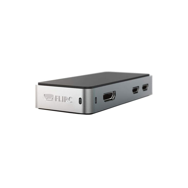
FLIRC FLIRC Case for Raspberry Pi Zero
The FLIRC Raspberry Pi Zero Case is compatible with Raspberry Pi Zero W and the newer Raspberry Pi Zero 2 W. The design of the FLIRC Zero Case is based on the original FLIRC case. As with the original, the aluminum housing serves as protection and, thanks to the contact point on the processor, as a passive cooler. Ideal for silent operation. In addition to a normal cover that encloses and protects the Raspberry Pi Zero, there is a second cover that allows access to the GPIO pins through a small opening.


