Produits
-

Elektor Digital The Bottle Builder (E-book)
The author, Johan Basse Bergqvist, is an engineer, a musician, and an audiophile with a knack for building projects that produce the desired results. The combination of these skills leads to a uniquely valuable perspective on audio design that is routinely reflected in the book and passed on to the readers. Several design projects are provided, 40 in total. The designs are explained, and the unique features or methods he uses are described in further detail. Each design includes detailed schematics and a complete parts list. Many of the projects also include layout documentation in the form of CAD photos of the PCB layouts. The range of projects is very diverse and includes something that will appeal to everyone. Stereo amplifiers, guitar and bass amplifiers, preamplifiers for phono, and microphones are all covered. Several variants for each type are included, and the power amplifier designs range from a few watts to several hundred watts, which meet almost any power level you might tackle.
€ 64,95
Membres : € 58,46
-
Elektor Publishing The CAN Bus Companion
This book details the use of the Arduino Uno and the Raspberry Pi 4 in practical CAN bus based projects. Using either the Arduino Uno or the Raspberry Pi with off-the-shelf CAN bus interface modules considerably ease developing, debugging, and testing CAN bus based projects. This book is written for students, practicing engineers, enthusiasts, and for everyone else wanting to learn more about the CAN bus and its applications. The book assumes that the reader has some knowledge of basic electronics. Knowledge of the C and Python programming languages and programming the Arduino Uno using its IDE and Raspberry Pi will be useful, especially if the reader intends to develop microcontroller-based projects using the CAN bus. The book should be a useful source of reference material for anyone interested in finding answers to questions such as: What bus systems are available for the automotive industry? What are the principles of the CAN bus? How can I create a physical CAN bus? What types of frames (or data packets) are available in a CAN bus system? How can errors be detected in a CAN bus system and how dependable is a CAN bus system? What types of CAN bus controllers exist? How do I use the MCP2515 CAN bus controller? How do I create 2-node Arduino Uno-based CAN bus projects? How do I create 3-node Arduino Uno-based CAN bus projects? How do I set the acceptance masks and acceptance filters? How do I analyze data on the CAN bus? How do I create 2-node Raspberry Pi-based CAN bus projects? How do I create 3-node Raspberry Pi-based CAN bus projects?
€ 34,95
Membres : € 31,46
-
Elektor Digital The CAN Bus Companion (E-book)
Projects with Arduino Uno & Raspberry Pi with Examples for the MCP2515 CAN Bus Interface Module This book details the use of the Arduino Uno and the Raspberry Pi 4 in practical CAN bus based projects. Using either the Arduino Uno or the Raspberry Pi with off-the-shelf CAN bus interface modules considerably ease developing, debugging, and testing CAN bus based projects. This book is written for students, practicing engineers, enthusiasts, and for everyone else wanting to learn more about the CAN bus and its applications. The book assumes that the reader has some knowledge of basic electronics. Knowledge of the C and Python programming languages and programming the Arduino Uno using its IDE and Raspberry Pi will be useful, especially if the reader intends to develop microcontroller-based projects using the CAN bus. The book should be a useful source of reference material for anyone interested in finding answers to questions such as: What bus systems are available for the automotive industry? What are the principles of the CAN bus? How can I create a physical CAN bus? What types of frames (or data packets) are available in a CAN bus system? How can errors be detected in a CAN bus system and how dependable is a CAN bus system? What types of CAN bus controllers exist? How do I use the MCP2515 CAN bus controller? How do I create 2-node Arduino Uno-based CAN bus projects? How do I create 3-node Arduino Uno-based CAN bus projects? How do I set the acceptance masks and acceptance filters? How do I analyze data on the CAN bus? How do I create 2-node Raspberry Pi-based CAN bus projects? How do I create 3-node Raspberry Pi-based CAN bus projects?
€ 29,95
Membres : € 26,96
-
Elektor Digital The Complete ESP32 Projects Guide (E-book)
59 Experiments with Arduino IDE and Python The main aim of this book is to teach the Arduino IDE and MicroPython programming languages in ESP32 based projects, using the highly popular ESP32 DevKitC development board. Many simple, basic, and intermediate level projects are provided in the book using the Arduino IDE with ESP32 DevKitC. All projects have been tested and work. Block diagrams, circuit diagrams, and complete program listings of all projects are given with explanations. In addition, several projects are provided for programming the ESP32 DevKitC using MicroPython. The projects provided in this book are designed to teach the following features of the ESP32 processor: GPIOs Touch sensors External interrupts Timer interrupts I²C and I²S SPI PWM ADC DAC UART Hall sensor Temperature sensor Infrared controller Reading and writing to SD card Reading and writing to flash memory RTC timer Chip ID Security and encryption Wi-Fi and network programming Bluetooth BLE programming Communication mobile devices Low power design ESP-IDF programming The projects have been organized with increasing levels of difficulty. Readers are encouraged to tackle the projects in the order given. A specially prepared hardware kit (SKU 18305) is available from Elektor. With the help of this hardware, it should be easy and fun to build the projects in this book.
€ 34,95
Membres : € 31,46
-

Elektor Classics The Complete Linear Audio Library (clé USB)
Jan Didden a créé Linear Audio en 2010 et a publié 14 volumes entre 2010 et 2017. Chaque volume de 200 pages contient en moyenne 10 articles rédigés par des auteurs experts dans le domaine de l'audio, de l'acoustique et de l'instrumentation. Que vous vous intéressiez aux amplificateurs à tubes, aux équipements à semi-conducteurs, à la conception de haut-parleurs, à la distorsion des condensateurs et des résistances ou à la mesure de la distorsion, vous y trouverez certainement des conseils utiles et des réflexions intéressantes. Du niveau débutant au niveau avancé, pour le professionnel de l'audio ou l'amateur sérieux, cette collection d'experts vous permettra d'améliorer votre compréhension et vous offrira de nouvelles perspectives sur des problématiques courantes. Le contenu bonus inclus dans cette collection est constitué d'une série YouTube en 5 parties sur le feedback négatif appliqué à l'audio par l'auteur renommé Jan Didden, en plus de neuf articles et présentations audio de référence. Si vous vous intéressez sérieusement à l'audio, à l'acoustique et à l'instrumentation, ne manquez pas cette collection ! Le contenu publié est indexé et entièrement consultable et constituera une ressource presque illimitée pour l'avenir. Vous pouvez en savoir plus sur les auteurs deLinear Audio et la table des matières de chaque volume à linearaudio.net.
€ 149,95€ 74,95
Meilleur prix
-

Elektor Publishing The Connected Autonomous Vehicle and its Environment
An Introduction to Real and Reduced-Scale Autonomous Vehicles Want to cut through the hype and get to the core of autonomous and connected vehicles? Then this book is your clear, accessible guide to a complex and fast-moving field. Starting with Intelligent Transport Systems (ITS), it walks you through the essential foundations, including Advanced Driver Assistance Systems (ADAS) – the stepping stones to full autonomy. Explore how self-driving cars mimic human behavior through a loop of perception, analysis, decision, and action. Discover the key functions that make it possible: localization, obstacle detection, driver monitoring, cooperative awareness – and the most challenging of all, trajectory planning, across strategic, tactical, and operational levels. Will vehicles be connected? The debate is on – but the standards are already here. Learn how connectivity, infrastructure, and vehicles can work in synergy through the innovative concept of floating car data (FCD). Dive into real-world implementation: with embedded electronics account-ing for over 30% of a modern vehicle‘s cost, we unpack the architecture, coordination, and tools required to manage the complexity – brought to life with a hands-on case study. To finish, we open the door to the future: building your own 1:10 scale autonomous vehicle. No plug-and-play solutions – just the foundations for a collaborative, creative, and geek-friendly challenge. Let’s drive the future together.
€ 34,95
Membres : € 31,46
-

Elektor Digital The Connected Autonomous Vehicle and its Environment (E-book)
An Introduction to Real and Reduced-Scale Autonomous Vehicles Want to cut through the hype and get to the core of autonomous and connected vehicles? Then this book is your clear, accessible guide to a complex and fast-moving field. Starting with Intelligent Transport Systems (ITS), it walks you through the essential foundations, including Advanced Driver Assistance Systems (ADAS) – the stepping stones to full autonomy. Explore how self-driving cars mimic human behavior through a loop of perception, analysis, decision, and action. Discover the key functions that make it possible: localization, obstacle detection, driver monitoring, cooperative awareness – and the most challenging of all, trajectory planning, across strategic, tactical, and operational levels. Will vehicles be connected? The debate is on – but the standards are already here. Learn how connectivity, infrastructure, and vehicles can work in synergy through the innovative concept of floating car data (FCD). Dive into real-world implementation: with embedded electronics account-ing for over 30% of a modern vehicle‘s cost, we unpack the architecture, coordination, and tools required to manage the complexity – brought to life with a hands-on case study. To finish, we open the door to the future: building your own 1:10 scale autonomous vehicle. No plug-and-play solutions – just the foundations for a collaborative, creative, and geek-friendly challenge. Let’s drive the future together.
€ 29,95
Membres : € 26,96
-
Elektor Digital The EAGLE Companion (E-book)
EAGLE – the “Easily Applicable Graphical Layout Editor“ is a professional-grade CAD (computer aided design) software package for the design and drafting of electronic schematics as well as the design and fabrication of printed circuit boards (PCBs). This Advanced User Guide provides the experienced EAGLE user with insight into using some of the more advanced features of EAGLE software. It is not a guide to teach the reader the basic concepts of EAGLE, nor does it discuss the ‘how to’ of the EAGLE interface and the simpler operations and commands of the software. That is the purpose of the author’s previous title EAGLE V6 Getting Started Guide also published by Elektor. This eBook is intended as an enduring document covering the more advanced modules, commands, and functions which make up EAGLE. It is hoped that this eBook will provide a quick, succinct reference to assist with more complex applications and uses of EAGLE – an ‘EAGLE User’s Companion’, if you like. Complementing the EAGLE Advanced User Guide, the EAGLE User Language manual is included in this eBook in unabridged form, reproduced with permission of CadSoft GmbH. At the time of writing, the material in this eBook covers version 7 of the EAGLE software suite.
€ 39,95
Membres : € 35,96
-
Elektor Classics The Elektor Arduino Collection (clé USB)
Cette clé USB contient une sélection de plus de 300 articles liés à Arduino publiés dans le magazine Elektor. Le contenu comprend à la fois des articles de fond et des projets sur les sujets suivants : Développement logiciel et matériel : tutoriels sur le développement logiciel avec l’IDE Arduino, Atmel Studio, les shield, et les concepts essentiels de programmation. Apprentissage : le Microcontroller Bootcamp propose une approche structurée pour programmer des systèmes embarqués. Acquisition et mesure de données : projets comme un enregistreur de données 16 bits, un tachymètre pour tour, et un analyseur de réseau électrique pour capturer et analyser des signaux en temps réel. Communication sans fil : apprenez à mettre en œuvre des réseaux sans fil, créer une interface Android, et communiquer efficacement avec des microcontrôleurs. Robotique et automatisation : le Arduino Nano Robot Controller, des cartes de support pour l'automatisation, et l'exploration de divers shield Arduino pour enrichir les fonctionnalités. Projets à construire soi-même : Des projets uniques tels qu’un projecteur laser, une horloge et un thermomètre Numitron, un récepteur TBF, Theremino, et des interfaces LED tactiles mettent en valeur des applications créatives. Que vous soyez débutant ou expérimenté, cette collection est une ressource précieuse pour apprendre, expérimenter et repousser les limites de la technologie Arduino.
€ 49,95€ 34,95
Meilleur prix
-

Elektor Classics The Elektor Audio Collection 2026 (clé USB)
Plus de 475 circuits audio issus de 30 ans d'Elektor Cette clé USB contient plus de 475 circuits audio extraits des numéros d'Elektor de 1995 à 2025. La fonction de recherche d'articles vous permet d'effectuer des recherches en texte intégral. Les résultats sont toujours affichés sous forme de documents PDF préformatés. Quelques points forts Décodeur Surround Ampli 50 W compact Convertisseur de taux d’échantillonnage Préamplificateur alimenté par piles Ampli Titan 2000 Crescendo-Millennium amplificateur Audio-DAC/ADC Émetteur/récepteur IR-S/PDIF Amplificateur Perfection Casque sans fil haute fidélité Commande de tonalité paraphase et plus… Sur la clé, vous trouverez également un dossier avec un contenu supplémentaire tel que des schémas de circuits imprimés, des fichiers Gerber et des logiciels. Spécifications Mémoire 16 Go Connecteurs 1x USB-A1x USB-C Matériel et logiciel requis Ordinateur avec Adobe Reader version 7 ou sup. Navigateur Internet Vous pourrez, par le biais du Reader d’Adobe, faire apparaître et rechercher les différents articles sur votre écran et imprimer les textes, schémas et dessins de platine.
€ 49,95€ 39,95
Meilleur prix
-
Elektor Classics The Elektor Circuit Collection 2025 (clé USB)
3K5 circuits mémorables (1975-2025) Cette clé USB contient plus de 3500 circuits mémorables dans tous les domaines de l'électronique (audio et vidéo, jeux et modélisme, domestique, processeur et microcontrôleur, test et mesure, alimentation et batteries) publiés dans Elektor Magazine depuis 1975. La plupart des circuits proviennent des éditions Elektor Summer Circuits. Une puissante fonction de recherche dans le texte intégral des articles permet de retrouver instantanément le contenu qui vous intéresse. Les résultats sont des documents PDF. Parcourez les articles un à un avec Adobe Reader ou cherchez partout les mots et les expressions de votre choix grâce à la fonction de recherche intégrée. Veuillez noter qu'aucune édition de Summer Circuits n'a été publiée entre 2014 et 2022, ces années ne sont donc pas incluses dans l'annuaire. Spécifications Stockage 32 Go Connecteurs 1x USB-A1x USB-C
-

Elektor Classics The Elektor Power Supply Collection 2026 (clé USB)
Plus de 275 circuits d'alimentation électrique « maison » Cette clé USB contient plus de 275 circuits d'alimentation électrique extraits des numéros d'Elektor de 2001 à 2025. La fonction de recherche d'articles vous permet d'effectuer des recherches en texte intégral. Les résultats sont toujours affichés sous forme de documents PDF préformatés. Quelques points forts convertisseur Cuk Automatic Battery Switchover LED de contrôle de piles alimentation de table numérique chargeur de pile Lithium-Ion chargeur à cellules solaires fusible électronique régulateur haute tension alimentation par le port USB convertisseur élévateur pour LED Battery Management et bien plus encore... Sur la clé, vous trouverez également un dossier avec un contenu supplémentaire tel que des schémas de circuits imprimés, des fichiers Gerber et des logiciels. Spécifications Mémoire 16 Go Connecteurs 1x USB-A1x USB-C Matériel et logiciel requis Ordinateur avec Adobe Reader version 7 ou sup. Navigateur Internet
€ 49,95€ 39,95
Meilleur prix
-

The Elektor RF & Communications Collection (clé USB)
Cette clé USB contient une sélection de plus de 350 articles sur les RF, la radio et la communication publiés dans le magazine Elektor. Le contenu comprend à la fois des articles de fond et des projets portant sur les sujets suivants : Circuits de base liés à la radio ainsi que circuits plus complexes comme des filtres, des oscillateurs et des amplificateurs. Conception, construction et théorie des antennes pour transmettre et recevoir efficacement des signaux radio. Conception et analyse de circuits RF, notamment filtres, mélangeurs, PLL et synthétiseurs de fréquence. Outils et techniques pour prédire les chemins de propagation des ondes radio et mesurer la force du signal RF. Techniques de traitement des signaux numériques dans les systèmes RF, y compris les méthodes de modulation et de démodulation. Projets sur les récepteurs radio, AM, FM, SSB, CW, DRM, DAB, DAB+, Software Defined Radio, et plus encore. Projets sur Wi-Fi, Bluetooth, LoRaWAN, et plus encore. Vous pouvez utiliser la fonction de recherche d'articles pour localiser un contenu spécifique dans le texte intégral. Les résultats sont toujours affichés sous forme de documents PDF préformatés. Vous pouvez utiliser Adobe Reader pour parcourir des articles et utiliser les fonctions de recherche intégrées d'Adobe Reader pour rechercher des instances de mots et d'expressions individuels.
€ 49,95€ 34,95
Meilleur prix
-
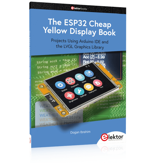
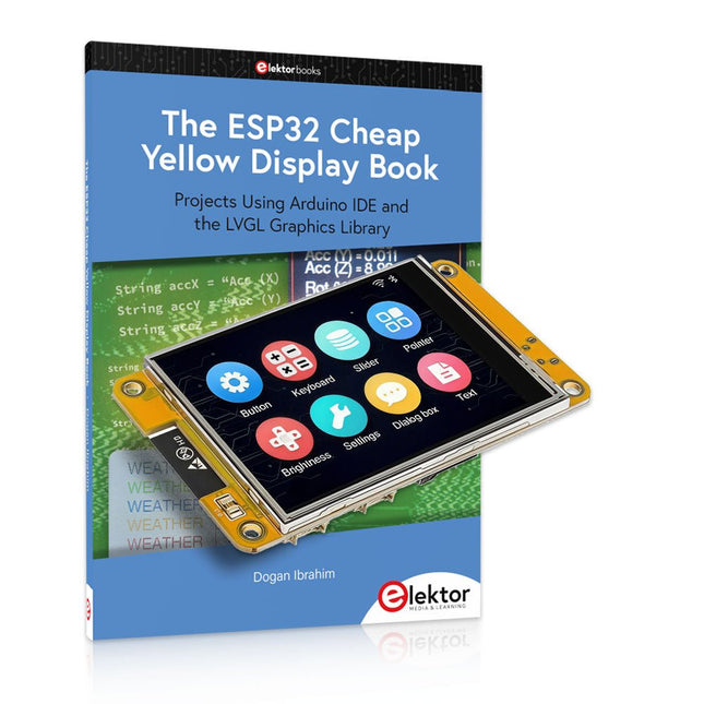
Elektor Publishing The ESP32 Cheap Yellow Display Book
Projects Using Arduino IDE and the LVGL Graphics Library The ESP32 is probably one of the most popular microcontrollers used by many people, including students, hobbyists, and professional engineers. Its low cost, coupled with rich features makes it a popular device to use in many projects. Recently, a board called the ESP32 Cheap Yellow Display (CYD for short) is available from its manufacturers. The board includes a standard ESP32 microcontroller together with a 320x240 pixel TFT display. Additionally, the board provides several connectors for interfaces such as GPIO, serial port (TX/RX), power and Ground. The inclusion of a TFT display is a real advantage as it enables users to design complex graphics-based projects without resorting to an external LCD or graphics displays. The book describes the basic hardware of the ESP32 CYD board and provides details of its on-board connectors. Many basic, simple, and intermediate-level projects are given in the book based on the ESP32 CYD, using the highly popular Arduino IDE 2.0 integrated development environment. The use of both the basic graphics functions and the use of the popular LVGL graphics library are discussed in the book and projects are given that use both types of approaches. All the projects given in the book have been tested and are working. The block diagram, circuit diagram, and the complete program listings and program descriptions of all the projects are given with explanations. Readers can use the LVGL graphics library to design highly popular eye-catching full-color graphics projects using widgets such as buttons, labels, calendars, keypads, keyboards, message boxes, spinboxes, sliders, charts, tables, menus, bars, switches, drop-down lists, animations, and many more widgets.
€ 34,95
Membres : € 31,46
-

Elektor Digital The ESP32 Cheap Yellow Display Book (PDF)
Projects Using Arduino IDE and the LVGL Graphics Library The ESP32 is probably one of the most popular microcontrollers used by many people, including students, hobbyists, and professional engineers. Its low cost, coupled with rich features makes it a popular device to use in many projects. Recently, a board called the ESP32 Cheap Yellow Display (CYD for short) is available from its manufacturers. The board includes a standard ESP32 microcontroller together with a 320x240 pixel TFT display. Additionally, the board provides several connectors for interfaces such as GPIO, serial port (TX/RX), power and Ground. The inclusion of a TFT display is a real advantage as it enables users to design complex graphics-based projects without resorting to an external LCD or graphics displays. The book describes the basic hardware of the ESP32 CYD board and provides details of its on-board connectors. Many basic, simple, and intermediate-level projects are given in the book based on the ESP32 CYD, using the highly popular Arduino IDE 2.0 integrated development environment. The use of both the basic graphics functions and the use of the popular LVGL graphics library are discussed in the book and projects are given that use both types of approaches. All the projects given in the book have been tested and are working. The block diagram, circuit diagram, and the complete program listings and program descriptions of all the projects are given with explanations. Readers can use the LVGL graphics library to design highly popular eye-catching full-color graphics projects using widgets such as buttons, labels, calendars, keypads, keyboards, message boxes, spinboxes, sliders, charts, tables, menus, bars, switches, drop-down lists, animations, and many more widgets.
€ 29,95
Membres : € 26,96
-
Elektor Bundles The ESP32 Cheap Yellow Display (offre groupée)
Plus de 40 projets ESP32 entièrement testés utilisant l'IDE Arduino et la bibliothèque graphique LVGL Cette offre groupée comprend l'ESP32 Cheap Yellow Display (CYD), une carte de développement compacte combinant un microcontrôleur ESP32 standard et un écran couleur TFT de 320 x 240 pixels. La carte dispose également de plusieurs connecteurs pour les GPIO, la communication série (TX/RX), l'alimentation et la masse. L'écran intégré est un atout majeur : il permet aux utilisateurs de créer des projets graphiques complexes sans écran LCD ni écran externe. Le livre d'accompagnement présente en détail le matériel et les connecteurs intégrés de la carte CYD. Il propose une gamme de projets de niveau débutant à intermédiaire, développés avec l'IDE Arduino 2.0. Les fonctions graphiques de base et la puissante bibliothèque graphique LVGL sont abordées, avec des projets pratiques illustrant chaque approche. Tous les projets inclus ont été entièrement testés et sont prêts à l'emploi. Le livre fournit des schémas fonctionnels, des schémas de circuits, des listes de codes complètes et des explications étape par étape. Avec la bibliothèque LVGL, les lecteurs peuvent créer des interfaces graphiques modernes et en couleur à l'aide de widgets tels que des boutons, des étiquettes, des curseurs, des calendriers, des claviers, des graphiques, des tableaux, des menus, des animations, etc. ESP32 Cheap Yellow Display Board Cette carte de développement (également connue sous le nom de « Cheap Yellow Display ») est alimentée par l'ESP-WROOM-32, un MCU double cœur avec des capacités Wi-Fi et Bluetooth intégrées. Il fonctionne à une fréquence principale allant jusqu'à 240 MHz, avec 520 Ko de SRAM, 448 Ko de ROM et une mémoire Flash de 4 Mo. La carte dispose d'un écran de 2,8 pouces avec une résolution de 240 x 320 et un toucher résistif. De plus, la carte comprend un circuit de contrôle du rétroéclairage, un circuit de contrôle tactile, un circuit de commande de haut-parleur, un circuit photosensible et un circuit de contrôle LED RVB. Il fournit également un emplacement pour carte TF, une interface série, une interface de capteur de température et d'humidité DHT11 et des ports IO supplémentaires. Le module prend en charge le développement dans Arduino IDE, ESP-IDE, MicroPython et Mixly. Applications Transmission d'images pour les appareils Smart Home Surveillance sans fil Agriculture intelligente Reconnaissance sans fil QR Signal du système de positionnement sans fil Et d'autres applications IoT Spécifications Microcontrôleur ESP-WROOM-32 (MCU double cœur avec Wi-Fi et Bluetooth intégrés) Fréquence Jusqu'à 240 MHz (la puissance de calcul peut atteindre 600 DMIPS) SRAM 520 Ko ROM 448 Ko Flash 4 Mo Tension de fonctionnement 5 V Consommation électrique env. 115 mA Écran Écran TFT couleur de 2,8 pouces (240 x 320) Toucher Toucher résistif Puce du pilote ILI9341 Dimensions 50 x 86 mm Poids 50 g Téléchargements GitHub Cette offre groupée contient : The ESP32 Cheap Yellow Display Book (prix normal : 35 €) ESP32 Cheap Yellow Display Board (prix normal : 25 €) 1x Carte de développement ESP32 avec écran de 2,8 pouces et boîtier en acrylique 1x Stylet tactile 1x Câble de connexion 1x Câble USB
€ 59,95€ 49,95
Meilleur prix
-

Würth The LTspice XVII Simulator (E-book)
Commands and Applications With more than 20 million users worldwide, LTspice XVII is the industry’s definitive electronic simulation software. The pure power, speed and accuracy of its simulations and its robustness make it an irreplaceable tool. This book is both an exhaustive operating manual for the latest version and an invaluable collection of examples and procedures with nearly 700 illustrations, covering everything from initially getting to grips with LTspice XVII to its exact application and extensive use. It will probably answer every question that’s likely to arise during training. All commands and definitions are detailed and classified by topic to make referencing the LTSpice XVII knowledge fast and easy.
€ 44,99
Membres : € 40,49
-

Raspberry Pi Foundation The Official Raspberry Pi Handbook 2025
Dive into the world of Raspberry Pi with this huge book of tutorials, project showcases, guides, product reviews, and much more from the writers of The MagPi, the official Raspberry Pi magazine. Raspberry Pi Pico 2 joins Raspberry Pi 5 in this, The Official Raspberry Pi Handbook 2025. Pico 2 comes with a faster processor than the original Pico, and uses less power – while still maintaining the same form factor and pinout. With both Pico 2 and Raspberry Pi 5 you can power any project you can imagine. With 200 pages packed full of maker goodness, you’ll also find inspiration for your Raspberry Pi Zero 2 W, Raspberry Pi 4, or any other Raspberry Pi model you have – there’s something for everyone. In this handbook you’ll find: A get started guide that covers every Raspberry Pi Everything you need to know about the brand-new Raspberry Pi Pico 2 Inspiring projects to spark your next build idea Tutorials for makers of all skill levels Guides for media centres, game emulators, and more! Raspberry Pi Pico 2 Microcontroller not included This bumper book is your definitive guide to everything Raspberry Pi. It’s essential for any maker with big dreams and a thirst for knowledge.
-
Elektor Digital The Raspberry Pi Zero 2 W GO! Book (PDF)
A Fast-Lane Ride From Concept to Project The core of the book explains the use of the Raspberry Pi Zero 2 W running the Python programming language, always in simple terms and backed by many tested and working example projects. On part of the reader, familiarity with the Python programming language and some experience with one of the Raspberry Pi computers will prove helpful. Although previous electronics experience is not required, some knowledge of basic electronics is beneficial, especially when venturing out to modify the projects for your own applications. Over 30 tested and working hardware-based projects are given in the book, covering the use of Wi-Fi, communication with smartphones and with a Raspberry Pi Pico W computer. Additionally, there are Bluetooth projects including elementary communication with smartphones and with the popular Arduino Uno. Both Wi-Fi and Bluetooth are key features of the Raspberry Pi Zero 2 W. Some of the topics covered in the book are: Raspberry Pi OS installation on an SD card Python program creation and execution on the Raspberry Pi Zero 2 W Software-only examples of Python running on the Raspberry Pi Zero 2 W Hardware-based projects including LCD and Sense HAT interfacing UDP and TCP Wi-Fi based projects for smartphone communication UDP-based project for Raspberry Pi Pico W communication Flask-based webserver project Cloud storage of captured temperature, humidity, and pressure data TFT projects Node-RED projects Interfacing to Alexa MQTT projects Bluetooth-based projects for smartphone and Arduino Uno communications
€ 32,95
Membres : € 29,66
-
Elektor Digital The State of Hollow State Audio (E-book)
The State of Hollow State Audio in the Second Decade of the 21st Century Vacuum-tube (or valve, depending upon which side of the pond you live on) technology spawned the Age of Electronics early in the 20th Century. Until the advent of solid-state electronics near mid-century, hollow-state devices were the only choice. But following the invention of the transistor (after their process fell to reasonable levels), within a couple of decades, the death of vacuum tubes was widely heralded. Yet here we are some five decades later, and hollow-state equipment is enjoying something of a comeback, especially in the music and high-end audio industries. Many issues surround hollow-state audio: Does it produce—as some claim—better sound? If so, is there science to back up these claims? How do hollow-state circuits work? How do you design hollow-state audio circuits? If hollow-state equipment fails, how do you go about troubleshooting and repairing it? Can we recreate some of the classic hollow-state audio devices for modern listening rooms and recording studios? How can we intelligently modify hollow-state amplifiers to our taste? These and other topics are covered in The State of Hollow State Audio.
€ 32,95
Membres : € 29,66
-
Elektor Digital The Ultimate Compendium of Sensor Projects (E-book)
40+ Projects using Arduino, Raspberry Pi and ESP32 This book is about developing projects using the sensor-modules with Arduino Uno, Raspberry Pi and ESP32 microcontroller development systems. More than 40 different sensors types are used in various projects in the book. The book explains in simple terms and with tested and fully working example projects, how to use the sensors in your project. The projects provided in the book include the following: Changing LED brightness RGB LEDs Creating rainbow colours Magic wand Silent door alarm Dark sensor with relay Secret key Magic light cup Decoding commercial IR handsets Controlling TV channels with IT sensors Target shooting detector Shock time duration measurement Ultrasonic reverse parking Toggle lights by clapping hands Playing melody Measuring magnetic field strength Joystick musical instrument Line tracking Displaying temperature Temperature ON/OFF control Mobile phone-based Wi-Fi projects Mobile phone-based Bluetooth projects Sending data to the Cloud The projects have been organized with increasing levels of difficulty. Readers are encouraged to tackle the projects in the order given. A specially prepared sensor kit is available from Elektor. With the help of this hardware, it should be easy and fun to build the projects in this book.
€ 34,95
Membres : € 31,46
-

tinySA tinySA Ultra+ ZS407 Analyseur de spectre
The tinySA Ultra+ ZS-407 is a compact, handheld spectrum analyzer and signal generator. Covering 100 kHz to 7.3 GHz in Ultra mode, it lets you visualize and analyze RF signals from HF right through many modern wireless bands – and can even spot signals up to ~12 GHz thanks to harmonic tracking. The intuitive 4-inch resistive touchscreen and rechargeable battery make it great for fieldwork, while features like a built-in signal generator, switchable bandpass filters, step attenuator, USB-PC control and auto-calibration add serious versatility. Caractéristiques Screen size: 4 inch (480 x 320) Spectrum Analyzer for 0.1-900 MHz or, with Ultra mode enabled up to 7.3 GHz, level calibrated up to 7.3 GHz. Can observe signals up to 12 GHz Signal Generator with sine wave output between 0.1-900 MHz or square wave up to 6.3 GHz or RF test signal output up to 7.3 GHz when not used as Spectrum Analyzer. Switchable resolution bandpass filters from 200 Hz to 850 kHz Built-in 20 dB optional LNA Color display showing max 450 points providing gapless covering up to the full frequency range. MicroSD card slot for storing measurements, settings and screen captures. Spécifications (Analyseur de spectre) Input frequency range from 100 kHz to 900 MHz in normal mode and up to 7.3 GHz with ULTRA mode enabled Input impedance 50 ohm when input attenuation set to 10 dB or more. Selectable manual and automatic input attenuation between 0 dB and 31 dB in 1 dB steps when LNA not active Maximum +/-5V DC input Absolute maximum input level of +6 dBm with 0 dB internal attenuation Absolute maximum short term peak input power of +20 dBm with 30 dB internal attenuation Suggested maximum input power of +0 dBm with internal attenuation in automatic mode For best measurements keep input power below -25 dBm Input Intercept Point of third order modulation products (IIP3) of +15 dBm with 0 dB internal attenuation 1 dB compression point at -1 dBm with 0 dB internal attenuation Power detector resolution of 0.5 dB and linearity versus frequency of ±2 dB below 5.3 GHz, ±5dB between 5.3 GHz and 6 GHz Minimum burst length for correct level measurement at 850 kHz RBW in zero span mode of 50 microseconds Absolute power level accuracy after power level calibration of ±2 dB Built-in optional 20 dB LNA with Noise Figure of 5 dB up to 6 GHz Lowest discernible signal without LNA at 30 MHz using a resolution bandwidth of 30 kHz of -102 dBm Lowest discernible signal with LNA at 30 MHz using a resolution bandwidth of 200 Hz of -145 dBm Frequency accuracy equal to the selected resolution bandwidth Phase noise at 30 MHz of -108 dB/Hz at 100 kHz offset and -115 dB/Hz at 1MHz offset Spur free dynamic range when using a 30 kHz resolution bandwidth of 70 dB Resolution filters with a width of 0.2, 1, 3, 10, 30, 100, 300, 600 and 850 kHz On screen resolution of 51, 101, 145, 290 or 450 measurement points. Scanning speed of over 1000 points/second using largest resolution filters. Automatic optimization of actual scanning points to ensure coverage of the whole scan range regardless of the chosen resolution bandwidth Spur suppression option for assessing if certain signals are internally generated or actually present in the input signal Headphone output for listening to the demodulated audio (AM only). Stereo connector with or without microphone, high impedance is louder, short protected Spécifications (Générateur de signaux) Sine wave output with harmonics below -40 dB of fundamental from 100 kHz to 900 MHz Output level selectable in 1 dB steps between -115 dBm and -19 dBm Above 800 MHz choice of two output modes: Cleanest signal mode: square wave, up to 6 GHz with coarse frequency steps and less accurate output level Highest accuracy mode: reduced harmonics with possibly strong spurs up to 7.3 GHz with frequency resolution equal to below 800 MHz and fine output level steps Level accuracy ±2 dB up to 800 MHz between -72 dBm and -19 dBm, less accuracy below -72 dBm, even less accuracy below -110 dBm Output frequency resolution 57.2 Hz Optional AM or FM modulation frequencies between 50 Hz and 5 kHz (AM) or 1 kHz (FM) or sweep over selectable frequency span AM modulation depth between 10% and 100% FM deviation between 1 kHz and 300 kHz Optional output level sweep over maximum the entire output level range Inclus 1x tinySA Ultra+ ZS407 Spectrum Analyzer 2x SMA connection cables 1x Barrel connector 1x Antenna with SMA connector 1x USB-C cable 1x microSD card (32 GB) Téléchargements Wiki
€ 194,40
-

Würth Trilogy of Connectors, 3rd Edition (E-book)
Contenu Principes de base Un connecteur est un système électromécanique qui assure une connexion séparable entre deux sous-systèmes d'un appareil électronique sans effet inacceptable sur les performances de l'appareil. Il sera démontré qu’il existe de nombreux paramètres complexes à gérer correctement pour que cette affirmation soit vraie. Conception / Sélection / Assemblage Ce chapitre donne un aperçu des exigences de conception et de matériaux pour les finitions de contact, les ressorts de contact et les boîtiers de connecteur ainsi que les principaux mécanismes de dégradation de ces composants de connecteur. Pour compléter ce chapitre, les critères de sélection des matériaux pour chacun seront également revus. De plus, le niveau d'interconnexion (LOI) a été intégré dans ce chapitre car il aborde l'endroit où le connecteur est utilisé dans un système électronique et influence donc les exigences et la durabilité du connecteur en fonction de son utilisation. Applications Ce chapitre s'oriente vers les travaux pratiques et montre comment les clients utilisent les connecteurs dans leurs applications pour offrir quelques possibilités et faciliter votre travail quotidien. De plus, il contient des sujets spéciaux tels que les moustaches en étain ou l'impédance du câble ZIF pour vous offrir des connaissances de base étendues.
€ 26,99
Membres : € 24,29
-

Würth Trilogy of Magnetics, 5th Edition (E-book)
Guide de conception pour la conception de filtres EMI, les circuits SMPS et RF Le livre se concentre sur la sélection de composants, de circuits et de recommandations de configuration pour un large éventail de composants magnétiques, en gardant toujours à l'esprit un point de vue CEM. Contenu Principes de base Les lois et fondements les plus importants des composants inductifs, les schémas de circuits équivalents et les modèles de simulation donnent au lecteur une connaissance de base en électronique. Composants Ce chapitre présente les composants inductifs, leurs propriétés particulières et leurs domaines d'utilisation. Tous les composants pertinents sont expliqués, des composants CEM et inductances aux transformateurs, composants RF, composants de protection de circuit, matériaux de blindage et condensateurs. Applications Dans ce chapitre, le lecteur trouvera un aperçu complet du principe des circuits de filtrage, des circuits et de nombreuses applications industrielles qui sont expliqués en détail à partir d'exemples originaux.
€ 44,99
Membres : € 40,49


